Change Dyad Closure / Change Configuration Assembly of a Dyad
Terminology
Dyad :
|
A dyad is an assembly of two Parts and three joints. Each Joint can be a Slide-Joint, a Pin-Joint, or a Ball-Joint. - One joint joins the two Parts together - The other two joints join the two Parts to two other Parts that are kinematically-defined. When you add the last joint, two Parts in the dyad will be kinematically-defined. |
Assur Groups : |
A different name for a dyad. |
Dyad Closures : |
The different ways you can assemble the two Parts of a dyad. Often, we will use the term Closure for Dyad-Closure. |
“Configuration of the Dyad's Assembly” is a different way to express “Dyad Closure”. It might be easier to translate |
|
Types of Dyad : |
Planar Dyads: R-R-R ; R-R-P ; R-P-R* ; R-P-P ; P-R-P Spatial Dyads: S-S-R ; S-S-P |
R : |
Revolute Joint = Pin-Joint |
P : |
Prismatic Joint = Slide-Joint |
S : |
Spherical Joint = Ball-Joint |
* |
This dyad does not correctly change its closure if the Pin-Joints(R) are offset from the Slide-Joint and along the y-axis of each Part in the dyad. |
See more: Dyads |
|
Change Dyad Closure
 RRR Dyad  Command-Manager: Change Dyad Closure  RRR Dyad |
STEP 1: Start the Change Dyad Closure command
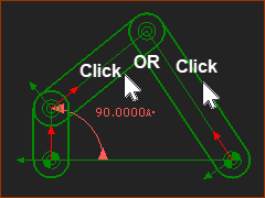
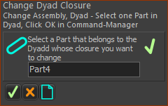
The Command-Manager indicates you must select a Part in the Dyad. STEP 2: Select one Part in the Dyad
STEP 3: Complete the Command
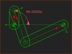
The configuration of the assembly (Dyad Closure) should now be different. <<< compare the bottom image with the top image. Note
STEP 4: Do again, to find the Dyad-Closure you want.
|
|||||||||||||||||
Top-Tip:
|
||||||||||||||||||
Assembly-Configurations of the R-R-P Dyad
|
|
The image below shows an Offset-Slider-Crank mechanism. |
|
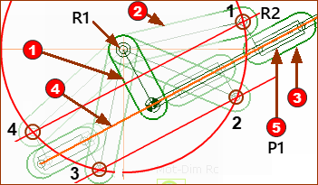
 4 x Assembly Configurations of an Offset-Crank-Slider |
|
Part Dyad: The Parts in the R-R-P dyad are Parts To imagine the four assembly-configurations, we imagine we have not yet added the Pin-Joint (R2) between Part Part Therefore, Pin-Joint R2 can ONLY be on the red circle at the end of Part Part Important: The Point in Part Therefore, Pin-Joint R2 can ONLY be on one of the red lines that are offset from the Slide-Joint. The red circle intersects the red lines at 4 places. Therefore, the Pin-Joint R2 can be at 4 places. Therefore, the Offset Slider-Crank and the R-R-P dyad has 4 possible assembly configurations (Dyad Closures). |