Step 6C1.3: Edit 3D-Cam; Save as STEP; Export directly to SOLIDWORKS®

<< Click to Display Table of Contents >>

Navigation:  Getting Started Tutorials - MechDesigner > Tutorial 6: Cams: Flat, Barrel, Globoidal, 'Slot' > 6C: Barrel-Cams & Globoidal-Cams > 6C1: Oscillating-Follower Barrel-Cam >

Step 6C1.3: Edit 3D-Cam; Save as STEP; Export directly to SOLIDWORKS®

Edit the 3D-Cam with the 3D-Cam dialog

Use the 3D-Cam dialog to edit the parameters that control the properties before you save or export the 3D-Cam in a different data format.

Save the Cam as different file-types. We recommend the STEP file-type. Open the STEP file in SolidWorks®, or your other 3D-CAD.

GST-6C1-301-Cam-Part

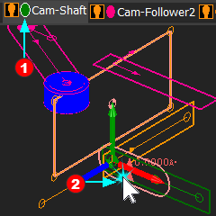
Frequently, you cannot see the 3D-Cam in the graphic-area.

STEP 1: Find the Cam-Part

The 3D-Cam is a child to the Cam-Part.

1.Click the Mechanism-name-tabRed-14-1 that has the Cam-Part as a child.

2.Click the Cam-PartRed-14-2 that has the 3D-Cam as a child.


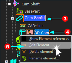
STEP 2: In the Assembly-Tree

The Cam-Part (Cam-Shaft1)

Red-14-3
is selected in the Assembly-Tree

The 3D-Cam is a child to the Cam-Part.

1.Explore the Cam-Part(Cam-Shaft1)

Red-14-4
to show the child elements

2.Right-click the 3D-Cam element

In the shortcut menu:

3.Click Edit Element

Red-14-5
in the shortcut menu

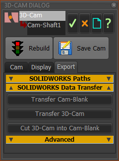
The 3D-Cam dialog is now open.


The 3D-Cam dialog has three tabs:

CAM tab - the design parameters

DISPLAY tab - color, display as 'solid', or as a 'mesh', ...

EXPORT tab - to export directly to SolidWorks.

It also has two buttons:

Rebuild-48 button

SaveCam-48 button


Use the Cam tab to increase the:

number-of-Points along each Rim

number of Rims along the Cam-Flanks, Floor, and Top surfaces.

clearances for the Follower-Roller.

Experiment.

GST-6C1-302-3D-Cam
3D-Cam dialog-box

3D-Cam dialog-box

btn_addkeywordSTEP file - recommended

STEP 1: MechDesigner - Save the 3D-Cam to a STEP file-type.

1.Click Rebuild button at the top of the 3D-Cam dialog

2.Click Save button

In the Windows Save as dialog, make sure the file-type is *.STP, and save the 3D-Cam as, e.g. Cam.STP

STEP 2: In SOLIDWORKS - Convert Cam.STP to a Cam.SLDPRT.

1.Open the Cam.STEP file in SolidWorks®

2.Agree to do: Import Diagnostics.

3.Close Import Diagnostics command

In the Feature Manager, the feature is Cam.stp<1> - >

Depending on your SolidWorks® user settings, you may also need to:

a)Right-Click Cam.stp<1> -> in the Feature Manager.

In the shortcut-menu:

b)Click Break Link, and, in the pop-up, select Yes, break the link

In the Feature Manager, the feature is Surface-Imported1.

c)Right-Click the feature in the Feature-Manager, again

In the contextual menu,

d)Click Import Diagnostic

In the Import Diagnostics dialog

e)Click the Attempt to Heal All button, and then close the Import Diagnostics command.

In the Feature Manager, the feature is Imported1.

4.Save your model as a SolidWorks Part document, with file-type (SLDPRT) E.g. Cam.SLDPRT.

STEP 3: In SOLIDWORKS

1.Do File menu > New > Part document

2.Do File menu > Save as > Cam-Blank.SLDPRT

STEP 4: In MechDesigner

1.Click 3D-Cam dialog > Export tab > SolidWorks Data Transfer > Transfer Cam-Blank button.

We export for you to SolidWorks the sketch of the Cam-Blank and the Rotation-Axis.

We instruct SolidWorks for you to add a Revolved Boss/Base feature from the sketch of the Cam-Blank and Rotation-Axis.

STEP 5: In SOLIDWORKS

SolidWorks receives the Cam-Blank sketch and

1.Do File menu > Save as > Cam-Blank.SLDPRT

STEP 6: In SOLIDWORKS continued ...

Combine the Cam.SLDPRT and the Cam-Blank.SLDPRT

The Cam-Blank.SLDPRT is the active SolidWorks document.

1.Insert menu > Part...  

2.Select the Cam.SLDPRT (See STEP 2.4)

3.Click OK in the feature manager.

In Feature Manager, there are now 2 Solid Bodies:

Revolve

<Cam><imported>

Do:

4.Insert menu > Feature > Combine.

5.Select Subtract as the Operation Type and, in the Bodies to Combine box, select Cam-Blank as the Main-Body and Cam<imported> as the Body to Subtract.

You should now see the Cam-Track cut into the Cam-Blank.


It is possible that the Solid Body Cam<imported> is not in the correct place relative to Cam-Blank. Most typically, Cam<imported> and Cam-Blank.SLDPRT are defined on different Planes.

In this case, you can redefine the sketch-planes of Cam.Blank (easiest method) or move Cam<imported>.

To move Cam<imported>, do:

1.Insert menu > Feature > Move/Copy... and select Cam.SLDPRT as the body to move.

btn_delkeywordEXPORT the Raw data to SOLIDWORKS®