Globoidal Cam with Indexing Output-Shaft
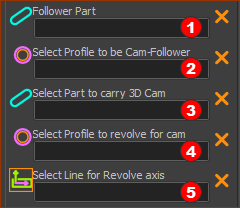
We add the 5 elements you need to design a Globoidal Cam
Globoidal Cams are also named Ferguson Cams or Roller Gear Drives.
In this Tutorial we:
1.Add the Cam-Part, Follower-Part, Follower-Rollers, Cam-Blank and Rotation-Axis - to different Mechanism-Editors. 2.Compare the Modified-Sine and Modified-Sine Constant-Velocity 33% motion-laws. 3.Add the Globoidal Cam. 4.Use the 3D-Cam dialog to configure the cam. 5.Export the 3D-Cam to SOLIDWORKS®. |
|
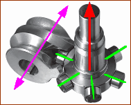
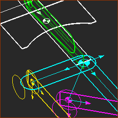
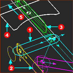
In the image, the:
|
||||||||||||||||
|---|---|---|---|---|---|---|---|---|---|---|---|---|---|---|---|---|---|
Commercial Globoidal Cams Commercial Globoidal Cams are sealed, oil-filled, cam-boxes. The cam-boxes are usually cast, machined, and bored to accurately locate the bearings of the input and output-shafts. An eccentric can adjust the distance from the output-shaft to the input-shaft. Shims adjust the cam along its axis. The output is a shaft or a flange-plate. The output-shaft may also be hollow. Dynamic Considerations Connect the input-shaft and output-shafts to other parts of the machine with zero backlash, torsionally-stiff couplings. Shafts should be as short as possible. Connect a geared-motor directly to the input-shaft, or as near as possible to it. The torque required to drive the input-shaft varies significantly as the output-shaft indexes. When referred to the motor, a high-ratio worm/wheel gear reduces the torque fluctuation significantly. Also, with efficient gearing, the motor behaves as a flywheel, which also reduces the speed variation of the input-shaft. If the input-shaft does not rotate at constant-velocity, the motion-law of the output-shaft will also be distorted from the planned motion. When the input-shaft accelerates and it rotates faster than planned, the acceleration and speed of the output-shaft may far exceed that of the planned motion. When the speed of the input-shaft is faster than planned, it is called over-run. Over-run can damage the Cam, Follower, Follower-Rollers, bearings, and/or the machine-components that you connect to the output-shaft. Input and Output motion exceptions Usually, the output-shaft indexes one time as the input-shaft rotates one time. The output-shaft may also need to index two or even three times as the input-shaft rotates one time, particularly when the index-angle is small. Read the catalogs carefully. A Cam from Destaco® North America.
|
|||||||||||||||||
 |
||
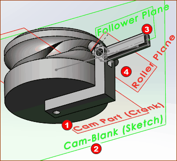
In MechDesigner, a Globoidal-Cam is built on four Planes.
Notes
|
|
|
STEP 1: Add the Cam-Shaft ( see example: Tutorial 1)
|
|
|
|
|
 Mod-Sine and 33% Constant Velocity |
|||||||||||||
See FULL DETAILS : MotionDesigner Tutorials > Tutorial 1 : Indexing Motion In MotionDesigner :
|
|||||||||||||
 |
Compare a Modified-Sine(MS) and a Modified-Sine with 33% Constant-Velocity (MSC33)
|
||||||||||||
|
|||||||||||||
 Mod-Sine 180 and 270 |
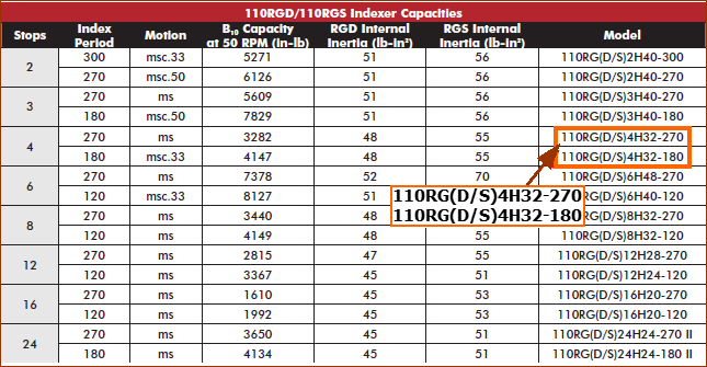
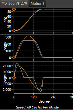
When the Index-Angle is large, the Pressure-Angle can be high and the width of the rib between the cam flanks can be small. To increase the width of the rib, reduce the Follower-Roller diameter, or use a Cam Motion-Law with a low maximum velocity. For information only: Compare the Peak Velocity and Acceleration Values of a Modified Sine Index-Period(β) 180º with those values when the Index-Period is 270º The image compares the two Modified-Sinusoid segments. Orange : Index-Period(β) = 270º , Dwell-Period = 90º Blue : Index-Period(β) = 180º , Dwell-Period = 180º Peak-Velocity : Modified-Sine (β=180º)=~315º/s ; Modified-Sine (β=270º) = ~235º/s Peak-Acceleration : Modified-Sine (β=180º)=~2200º/s/s ; Modified-Sine (β=270º)= ~980º/s/s. Ratios are ~134% Peak-Velocity, ~225% Peak-Acceleration. |
||||||||||||
The output-shaft:
|
|||
 |
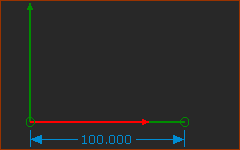
STEP 1: Add a Line to the Base-Part
|
||
 |
STEP 2: Add a Plane to the Line
|
||
 Image of the new Plane - +Z-axis is up. |
Plane •+Z-axis •Origin (0,0) : start-Point of Line STEP 1: Add a Mechanism to the new Plane
You jump to the new Mechanism-Editor. To see kinematic and sketch-elements in each Mechanism-Editor, you must:
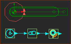
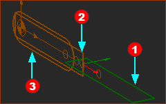
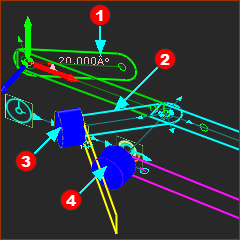
The elements in the image to the left are: •Base-Part •Base-Part |
||
 |
|||
 |
STEP 4: Add the Follower to the new Mechanism-Editor (Follower)
|
||
 |
STEP 5: Add Function-Blocks to control the Motion of the Follower
|
||
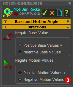 |
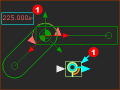
STEP 6: Edit the Motion-Dimension FB The Follower (output-shaft) rotates 4 x 90º to rotate a total of 360º. We want to move it in the negative direction.
|
||
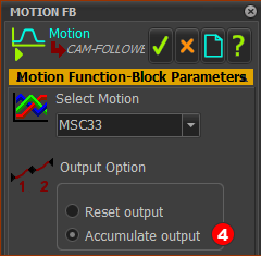 |
STEP 7: Edit the Motion FB
STEP 8: Rename the three(3) elements to Follower:
If you duplicate an elements's name, we add for you a number to the end of the element's name. e.g.: Follower1, Follower2, Follower3, ... |
||
Note: The Globoidal Indexer is a Body Closed Cam. During its dwell-period, two Follower-Rollers brace across the cam-flanks on the flanks of the cam, to give the Body-Closed construction. Also, a third Follower-Roller runs inside a groove during the dwell-period. Thus, a total of three Follower-Rollers are in contact with the cam during the dwell-period - which is over-constrained. The groove for the third Follower-Roller that runs in the middle of the cam may be cut wider than the Follower-Roller during the dwell-period. The L10 life of the Follower-Roller is longer and it will not scuff the cam surface as much, during the dwell. This Follower-Part has eight Follower-Rollers. They are at equal angles around the Follower-Part as a dial, a turret, or a star. We will see we need to add two 3D-Cams to the model. For this, we can add two Follower-Rollers, or we can design one 3D-Cam with one Follower-Roller, then edit the Base-Value of the Follower Part to add the other 3D-Cam with the same Follower-Roller. It is easier to see with 2 × 3D-cams with two Follower-Rollers in one model at the same time. We can use a Pattern to show the other 6 Follower-Rollers. The axis-of-rotation of each Follower-Roller is normal(⊥) to the axis-of-rotation of the Follower. To add 2 × Follower-Rollers, we must add 2 × Planes that are normal to the Follower Part. The Planes must at 45º to each other. We will add Lines, and Planes to the Lines, and Mechanism-Editors to the Planes . We will then add the Follower-Rollers in these new Mechanism-Editors. |
|||
|
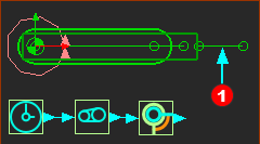
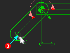
STEP 1: Add 2 × Lines to the Follower (output-shaft) (See 3 above)
|
||
|
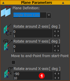
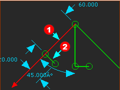
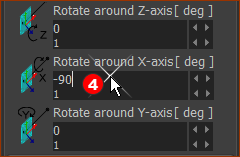
STEP 2: Add 2 × Planes to the short Lines
|
||
|
Note: Plane dialog: the order of the X,Y,Z parameter boxes can change! |
||
|
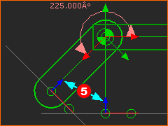
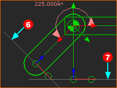
The Blue +Z-axes
The edges of the two Planes are in the image. The Planes are perpendicular to the Front-View (F3). |
||
|
STEP 3: Add 2 × Mechanism-Editors to the 2 × Planes
STEP 4: Rename elements
|
||
|
Do STEPS 1, STEP 2 and STEP 3 in Mechanism-Editors Follower-Roller-A and Follower-Roller-B STEP 1: Add a Circle and Profile
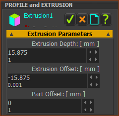
STEP 2: Add a Profile/Extrusion for the Follower-Roller
STEP 3: Edit the Extrusion for the Follower-Roller
STEP 4: Do STEPS 1 -3 again to add the extrusion for Follower-Roller B Notes
|
||||
|
|||||
|
|||||
|
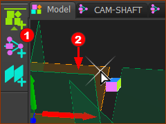
To Display Elements
The elements in the image are:
|
We must add a sketch for the Cam-Blank. The sketch is an approximation of the Cross-Section of the cam material immediately before you machine the Cams. |
||||
|
STEP 1: Add a new Mechanism-Editor to the Top Plane
You will jump to the new Mechanism-Editor. Rename the Mechanism-Editor to Cam-Blank |
|||
|
STEP 2: Edit the Base-Part to add the sketch of the Cam-Blank
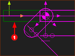
<<< The image is the Front-View (F3) of the Mechanism-Editor BEFORE we add the sketch of the Cam-Blank. |
|||
 Sketch of Cam-Blanki Part-Editor |
Notes
|
|||
 Cam-Blank in Mechanism-Editor |
<< The image is the sketch of the Cam-Blank with the model and mechanism elements. The Master Machine Angle puts the Follower-Rollers at the end of one index motion cycle. STEP 3: Add a Profile/Extrusion to the Cam-Blank
STEP 4: Edit the Extrusion for the Cam-Blank.
|
|||
|
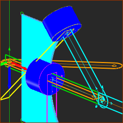
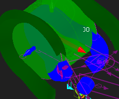
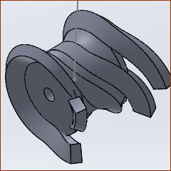
The image is the model after we have add the Cam-Blank sketch and a Profile / Extrusion. I have used my keyboard arrow-keys to spin the model. The MMA is not at 0 to make it easier to see Cam-Shaft. |
|||
Note - Correct the angle of the Follower when the MMA=0.
|
|||||
|
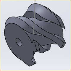
The image shows the Follower in the correct position. STEP 1: Before we do Add 3D-Cam
|
||||
|
STEP 2: Click Machine elements toolbar > Add 3D-Cam |
||||
|
STEP 2: Machine-element toolbar > Add 3D-Cam
The Command-Manager has five selection boxes. |
||||
|
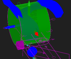
STEP 3: Select the elements to add 3D-Cam
The 3D-Cam is now in the Graphics-Area |
||||
|
Questions:
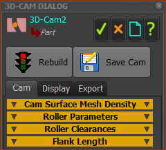
STEP 1: Edit the 3D-Cam
The 3D-Cam dialog has three tabs: Cam | Display | Export |
||
|
|||
|
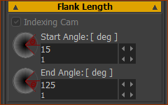
STEP 2: Edit the Flank-Length
|
||
|
|
||
|
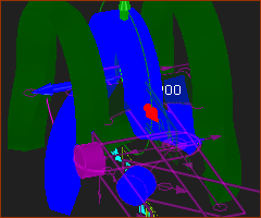
STEP 3: Add 3D-Cam 2 Prepare the View again :
|
||
|
STEP 4: Edit the 3D-Cam
Close the 3D-Cam dialog or see below: 9: Export the 3D-Cam to SolidWorks |
|
Start SOLIDWORKS®:
In MechDesigner :
In SOLIDWORKS®:
|
|||
|
In MechDesigner :
In SOLIDWORKS®:
|
|||
|
||||
|
In SOLIDWORKS®:
|
|||
|
In SOLIDWORKS®:
IMPORTANT NOTE: You should machine the flanks of Globoidal Cams, with a milling tool that has a diameter as near to possible to the diameter of the Follower-Roller. Tools with a diameter that is smaller than Follower-Roller have a machining error. The larger the difference in diameters, the larger the error between the 'true cam' as provided by MechDesigner, and the cam that you will actually machine. |
![]() Alternative to STEP File: Export the 3D-Cam Mesh data
Alternative to STEP File: Export the 3D-Cam Mesh data
STEP 1.Open the 3D-Cam dialog and Edit the 3D-Cam settings:
3D-Cam dialog
STEP 2.Send the Cam to SOLIDWORKS
|