Add a Simple Gear-Pair with Fixed centers
Simple Gear-Pair - Prepare
|
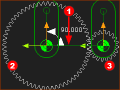
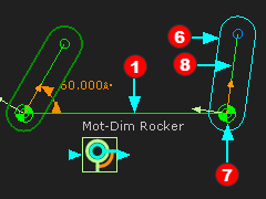
STEP 1: Add a Line to a Part that is kinematically-defined
|
|
|
STEP 2: Add a rotating-Part that is kinematically-defined
Part |
|
|
STEP 3: Add a rotating-Part that is free
|
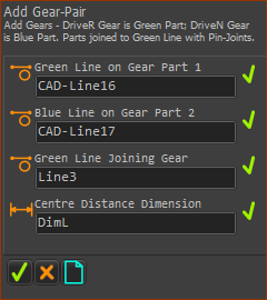
Add Gear-Pair
|
STEP 1: Start the Add Gear-Pair command
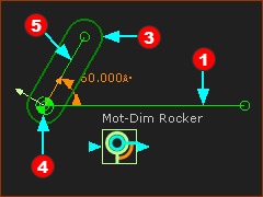
The Command-Manager has four selection-boxes. STEP 2: Select the four elements
STEP 3: Complete the command
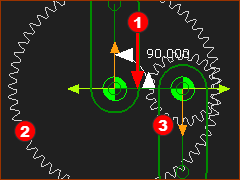
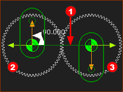
The default Gear-Pair has an External Mesh, and the gears have equal number-of-teeth. |
||||
|
The default Gear-Pair parameters •External tooth form (also called External Mesh) •Number-of-Teeth - Teeth on Driving Gear •Module is almost random! The Length-dimension of Line |
Video - Add Gear-Pair

Video - Gear-Pair with fixed centers
Basic Parameters: Number-of-Teeth, Module and Mesh
Open the Gear-Pair dialog to edit the Gear-Pair parameters. E.g: double-click a gear, or see How to open a dialog. |
|
|
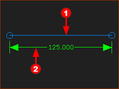
Mesh: External Gear Pair dialog > Define tab > Gear Mesh & Number-of-Teeth > Mesh : External •Number of Teeth, z1 (Driving-Gear) : 60 •Number of Teeth, z2 (Driven Gear) : 20 Gear Pair dialog > Parameters tab > Gear Tooth Parameters: > •Module, m : 2 Length of Line |
|
Mesh: Internal. Gear Pair dialog > Define tab > Gear Mesh & Number-of-Teeth > Mesh : Internal The Gear with fewer teeth moves inside the other Gear. An internal mesh is not possible when the Gears have equal number-of-teeth. When the Gears have an internal mesh, we subtract the number of teeth to find the length of the Line of centers. Length of Line |