Selection-Window
The Selection-Window is at the top of the Project-Explorer.
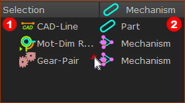
The Selection-Window shows the list of elements that you Click or Shift+Click in the graphics-area or select in the Element-Explorer.
Click ... any element in the graphics-area or Element-Explorer
 Elements in the Selection-Window |
Selection list The list of elements that you Click with your mouse in the graphics-area or Element-Explorer. Owner list “Mechanism”: when the element is a child to a Mechanism-Editor. “Part”: when the element is a child to a Part. |
Shift + Click ... sketch-elements to list constraints added to them
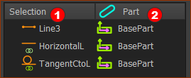
You cannot see in the graphics-area any Constraints that you have added to sketch-elements. You can, however, list the Constraints in the Selection-Window. To list in the Selection-Window a sketch-element and the constraints that you have added to it: 1.SHIFT + Click a sketch-element |
|
 Constraints in the Selection-Window with SHIFT+CLICK |
Selection-Window Selection list Sketch-Element that you SHIFT + Click, AND Constraint that you have added to the sketch-element - for example HorizontalL, AND Constraints that are between the sketch-element and a different sketch-element - for example TangentCtoL, Owner list Part - the Part to which you have added the sketch-element or Constraint. |
Shift + Click ... Profiles to list the Extrusion
To list an Extrusion in the Selection-Window: SHIFT + Click the Profile to list the Profile and the Extrusion that is a child to the Profile. |
|
 You can EDIT the Extusion |
Selection list The Profile that you SHIFT + Click The Extrusion that is a child to the Profile. Owner list Part: the Part to which the Profile is a child. |
Shortcut menu
 Shortcut menu in Selection-Window |
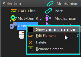
To show the shortcut menu 1. Use the shortcut menu to: •Show Element References - see below •Edit element •Delete element •Rename element •Show or Hide Extrusion - if you right-click an Extrusion |
Show Element References
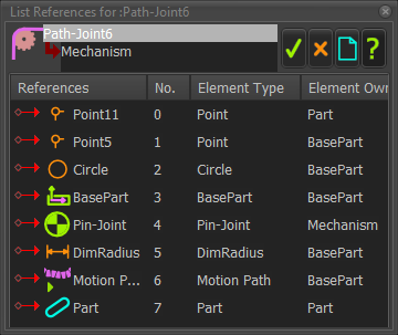
Many elements need other elements to exist in the model. The other elements are Reference Elements. For example, the Reference Elements of a: •Line are its start-Point and end-Point •Pin-Joint are two Points, which may be the start-Point or end-Point of a Line or the center-Point of a Circle. |
|
 Reference Elements for a Pulley |
|
The columns in the dialog identify the element's:
|