Extrusions, Profiles, Auto-Profile, and Auto-Profiles
A Profile is two offset-contours that are copies of a sketch-loop. We add the two contours for you when you do Add Profile, Add Auto-Profile, or Add Auto-Profiles. At the same time as you add Profile and Auto-Profile elements, we also add for you the Extrusion element. The Extrusion is the MD-Solid that is between the two Profile contours. •To edit the shape of the Profile you must edit the shape of the sketch-loop. •To edit the Extrusion-Depth, Extrusion-Offset, color, density, ... you must edit the Extrusion with the Extrusion dialog. •To see the two Profile contours, spin the model. •To see the Extrusion you must enable Show Solids in Mechanisms. |
Commands and Auto-Profiles
These commands - in the Solids toolbar - add sketch-loops and Auto-Profiles to Parts.
|
Solids menu (or toolbar) > Add Auto-Profile To add a sketch-loop and an Auto-Profile element to one Part that you select in the Mechanism-Editor. If you do Auto-Profile to a Part that has an Auto-Profile, you remove the Auto-Profile and sketch-loop from the Part. |
|
Solids menu (or toolbar) > Add Auto-Profiles To add a sketch-loop and an Auto-Profile element to all of the Parts in the Mechanism-Editor. If you do Auto-Profiles again, and if more than 50% of the Parts have Auto-Profiles, you remove the Auto-Profiles and sketch-loops from the Parts. |
|
Solids menu (or toolbar) > Auto Layer (optionally use with Auto Profiles) To offset the Auto-Profiles by different distances. When you cycle your mechanism, the Parts should not collide with each other (no guarantees). |
To see the MD-Solids in the graphics-area you must enable: |
|
|
Visibility menu > Show Solids in Mechanism |
Use the Auto-Profiles and Auto-Layer commands
|
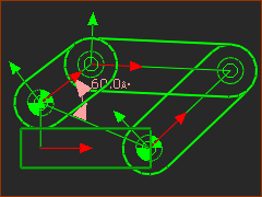
STEP 1: Complete or open Tutorial 2
STEP 2: Add Auto-Profiles to all of the Parts
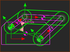
We add for you Auto-Profiles and sketch-loops to the Base-Part and each Part you in the model. <<< In the image, the Auto-Profiles are PINK. STEP 3: Show the Solids
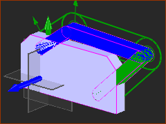
Now you should also be able to see the Extrusions in the Mechanism-Editor. STEP 4: Spin the model to see the Extrusions
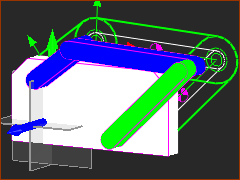
STEP 5: Layer the Profiles/Extrusions
Each Auto-Profile and Extrusion moves a different distance from the Mechanism-Plane. Alternatively, you can edit each Extrusion with the Extrusion dialog to edit the Extrusion-Offset and/or Part-Offset. |
||||||||
|
|||||||||
|
|||||||||
|
|||||||||
SummaryDo Auto-Profiles
Do Auto-Layer
|
|||||||||
Video of the Auto-Profile command

Add Auto-Profiles to a Kinematic-Chain