Add Profile and Add Hole
Add-Profile : add a Profile to a sketch-loop
Add-Hole : add a Hole to a sketch-loop to cut through a Profile.
Profile and Extrusion elements
•A Profile is two offset contours that are copies of a sketch-loop
•The Extrusion is automatically added to the model with the Profile.
•The Extrusion fills the gap between the Profile contours
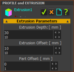
The Extrusion has parameters that you can edit with the Extrusions dialog:
•Parameters: Color, Transparency, Density.
•Distances: Part Offset, Extrusion Offset, Extrusion Depth
Note: The Profile/Extrusion is a Solid we call MD-Solid. The other type is a CAD-Solid, which you import from CAD onto a CAD-Line.
|
STEP 1: Add a sketch-loop to a Part
|
||
|
STEP 2: Start the Add Profile command
|
||
|
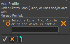
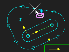
STEP 3: Select a sketch-element
|
||
|
STEP 4: Complete the Command
|
||
|
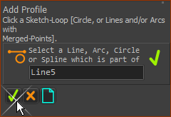
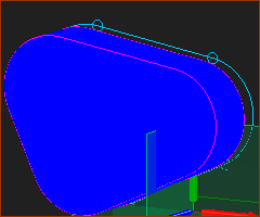
The Profile contours are (default) PINK In the Front-View the Profile contours hide the sketch-loop. Note: You can edit the color of the Profile contours in Application Settings | Graphics tab : Display Colors. |
||
|
The Profile and Extrusion in the Assembly-Tree If you expand the Mechanism element in the Assembly-Tree, you see the: •Part •The Profile •The Extrusion
|
||
|
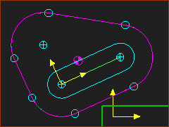
The Profile and Extrusion in the graphics-area The Profile has two contours - the Primary-Contour The default position of the Primary Contour is coplanar with the sketch-loop, and Mechanism-Plane.
|
||
|
STEP 5: Open the Extrusion dialog
The Extrusion dialog is open. STEP 6: Edit the Extrusion
|
||
|
|||
|
Show the Extrusion in the Mechanism-Editor use : •Enable Visibility toolbar > Show Solids in Mechanisms.
Hide the Extrusion again: •Disable Visibility toolbar > Show Solids in Mechanisms. |


|
STEP 1: Edit the Part
The Part-Editor is now open STEP 2: Start the Add Circle command
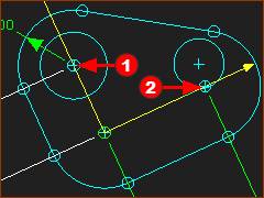
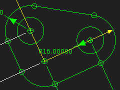
STEP 3: Add two Circles. Use these two techniques.
|
|||||||
|
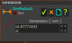
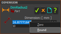
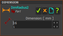
STEP 4: Add Dimensions and Constraints
|
|||||||
|
||||||||
|
||||||||
|
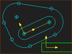
You have fully-defined the Circles: •the centers are coincident with Points in the Part •the Radii are equal; one has a dimension The sketch is Green in the Part-Editor to show it is fully-defined. 4.Close the Part-Editor – Double-click a sketch-element. We will now add the Holes through the Extrusion. |
|||||||
|
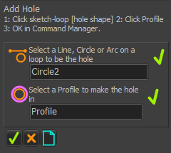
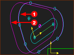
STEP 1: Do Add Hole
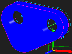
The Holes have cut through the Profile/Extrusion. |
||
|