Summary of this Step
1.Add a Part - we will rename it to Tool-Part. 2.Sketch the shape of the Tool - to practice using the Part-Editor. 3.Add a Slide-Joint between a Line in the Tool-Part and a Line in the Base-Part. |
Video (Step 6A.1)

Video: Add Tool-Part
STEP 1: Add a new Mechanism-Editor to the Front-Plane
|
||||||
 |
||||||
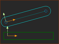
STEP 2: Add the Tool-Part
|
||||||
 |
||||||
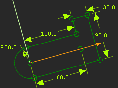
STEP 3: Edit the Tool-Part and add a sketch-loop
|
||||||
 |
||||
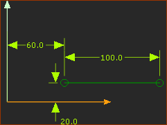
STEP 1: Add a Line to the Base-Part (See the image above)
|
||||
 |
||||
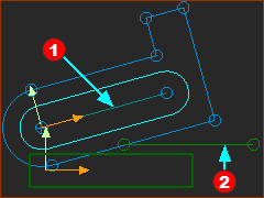
STEP 2: Add a Slide-Joint between Tool-Part and Base-Part.
Save your Mechanism (CTRL+S) |
||||
 The Symbol for a Slide-Joint |
|
The complete symbol for the Slide-Joint is:
|