Summary of this Step
To add a Linear-Motion FB, a Motion FB, and a Motion-Dimension FB to control the motion of the Tool-Part. |
Video of this Step
Video: Add the Motion to the Tool
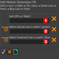 |
STEP 1: Start the Add Motion-Dimension FB command
In the Command-Manager there are three selection-boxes. |
||
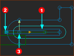 |
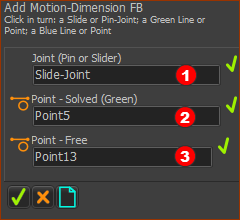
STEP 2: Select the three elements in the graphics-area See the image for three elements
The elements should be in the selection-boxes of the Command-Manager - see image to the left. |
||
 |
STEP 3: Complete the Command
The Motion-Dimension and the Motion-Dimension FB are in the graphics-area - see below. |
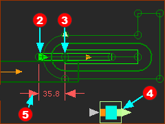 |
The Motion-Dimension
See also : Application-Settings > Graphics > Graphic Colors | Part Solved, Part Not Solved |
|
Note:
|
||
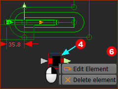 Shortcut menu 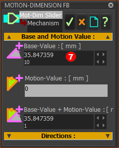 Motion-Dimension dialog |
The Base-Value is the value of the Motion-Dimension, and position of the Slider, when a wire is not connected to its input-connector, or the motion-value at its input is zero. STEP 1: Open the Motion-Dimension dialog
The Motion-Dimension dialog is open. |
|
STEP 2: Edit the Base-Value parameter
|
| Add a Linear-Motion FB, and a Motion FB and Connect Wires |
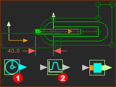 Three Function-Blocks - without wires |
STEP 1: Add two(2) Function-Blocks to the graphics-area The Kinematic FB toolbar is to the right(>>) of the graphics-area.
The Linear-Motion FB STEP 2: Connect he Function-Blocks with wires.
There are now wires between the Function-Blocks |
|||||
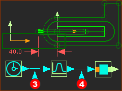 Three Function-Blocks - with wires |
||||||
The Motion-Dimension (that controls the position of the Slider) is equal to the Base-Value parameter PLUS the motion-value at the input-connector of the Motion-Dimension FB. |
||||||
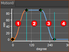 Default Motion |
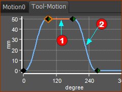
Default motion: You can link the Motion FB to one of the motions that has a Motion name-tab. The default motion has four Segments and four Blend-Points
* units of the Y-axis are mm or degrees. |
||||||||||||||||||
 1: File toolbar |
Usually, the default motion is not the motion that you need! I usually leave Motion0 untouched. STEP 1: Add a new motion to the list of Motion name-tabs.
There is now a Motion name-tab : Motion1 |
||||||||||||||||||
 2: Motion name-tab |
STEP 2: Rename Motion1 Motion1 is not a very imaginative name for a motion.
|
||||||||||||||||||
 3: New Motion name=tab: Tool-Motion |
|
STEP 1: Start the Blend-Point Editor in MotionDesigner
|
||||||||||||||||||
|
STEP 2: Use the Blend-Point Editor to give rise of 50mm
|
||||||||||||||||||
See also : |
|||||||||||||||||||
|
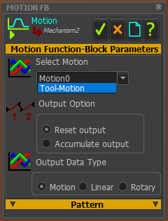
STEP 1: Link Tool-Motion to the Motion FB
STEP 2: Run the Model
The Slider will move with a displacement of 50mm. The minimum Motion-Dimension is 40mm and maximum is 90mm. Save your Mechanism |

