This topic provides a general review of the Servo and Gearbox Sizing Dialogs.
Kinetostatic Motor Torque and Speed dialog - MD14.2
Note: This topic has been updated to describe the new functionality in MD14.2
Note: The options for a Linear Motor with a Slide-Joint will become available in a later release.
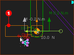
Make sure: •Force toolbar > Calculate Force is active •Visibility toolbar > Forces Vectors is active (MD14.2+ Force toolbar > Show Force Vectors ) You will see the Motor-Symbol at a joint If you want the Motor and Gearbox to be at a different joint, then use: •Force toolbar > Configure Power Source to move the motor to the correct joint. |
|
 |
To see the Motor-Symbol, you must use: Force toolbar > Show Force 1.Click the Motor-Symbol The Pin-Joint is in the Selection-Window 2.Right-Click the Pin-Joint 3.Click Edit element in the shortcut-menu - or - The Kinematic Torque and Speed dialog opens. |
 vs SPEED") FOUR QUADRANT: TORQUE(LOAD) vs SPEED |
When you open the Kinetostatic Torque-Speed dialog, you will see a plot of the Application (or Load) Torque vs Speed in all Four-Quadrants. Four-Quadrant - Why 4 Quadrants Many mechanism applications, when inertia is a significant or dominant load, require the servo-motor to apply: •Positive Torque - when accelerating in the positive direction and also decelerating in the reverse-direction •Negative Torque - when decelerating in the positive direction and also accelerating in the reverse-direction. •Positive angular velocity - when advancing the mechanism •Negative angular velocity - when returning the mechanism |
1.Auto-Filter check-box The Auto-Filter check-box is at the Top and Right of the dialog. ❑ Auto-Filter OFF When Auto-Filter is off, you can select from 1000s of Gearboxes. ☑Auto-Filter ON Click the check-box to make the Auto-Filter active. We recommend you select Auto-Filter. Auto-Filter ON, : MechDesigner offers for selection only those Gearboxes that have, as a Lower-Limit, the Torque and Speed capacity to drive the Application Load. The Upper-Limit of Gearboxes that MechDesigner presents for selection is determined with the Range-Factor. 2.Range-Factor The Range-Factor is bottom and left of the dialog. Auto-Filter ON pre-filters Gearboxes to those that have as a minimum capacity the Torque and Speed capacity to drive the Application (Load) Range-Factor pre-filters Gearboxes to those do not exceed Application-Load × Range-Factor. |
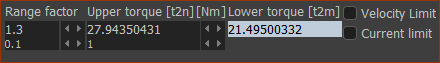 |
Example: Auto-Filter ON, Range-Factor: 1.3 Lower Gearbox Torque Capacity = Equivalent Application (Load) Torque (21.495 N.m.) Upper Gearbox Torque Capacity = Range Factor × Equivalent Application (Load) Torque (1.3 × 21.495 = 27.944 N.m.) |
Select a Gearbox Manufacturer
|
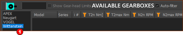 Note: If you need us to list a different Gearbox Manufacturer, then please email us. |
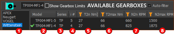
Select a Gearbox Model
|
|||||||||||||||||||||||||||||||||||||||||
|
T2max ≤ T2MAX ≤ RF × T2max Maximum Application (Load) Torque ≤ Maximum Output Torque of the Gearbox ≤ Range-Factor × Maximum Application (Load) Torque T2m ≤ T2N ≤ RF × T2m Equivalent Application (Load) Torque ≤ Rated Output Torque Capacity of the Gearbox ≤ Range-Factor × Equivalent Application (Load) Torque n2max× i ≤ n1MAX Maximum Application (Load) Speed × Gearbox Ratio (i) ≤ Maximum Input Speed of the Gearbox n2n × i ≤ n1N Average Application (Load) Speed (or Equivalent, Mean) × Gearbox Ratio (i) ≤ Rated Input Speed of the Gearbox |
||||||||||||||||||||||||||||||||||||||||
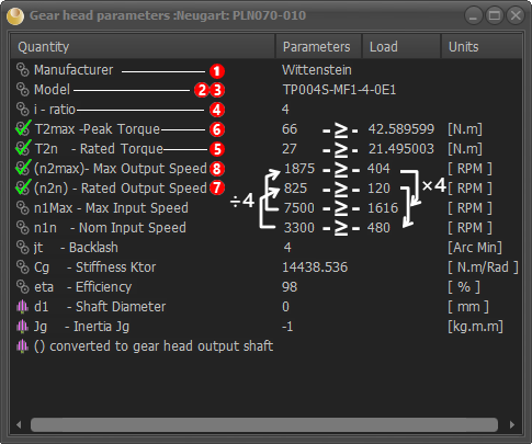 |
When you select a Gearbox model, its Gearbox Parameters Summary Sheet will show. This form is read only. We have selected a Gearbox with a Ratio, i = 4 The
Notes: Parameters in ( ) are referred to the output-shaft. Other Parameters include: •Backlash •Stiffness •Efficiency •Shaft Diameter - the input shaft diameter, which is not in the list until you select a Servomotor. •Inertia - referred to the input, which is not in the list until you select a Servomotor. |
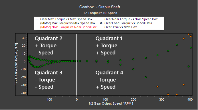 |
When you select a Gearbox, the Torque (N.m.) vs Speed (RPM) plot changes to indicate whether the Gearbox has the Capacity to drive the Application Load or not. The color code is : •Green : Torque AND Speed of the Load ≤ Rated Gearbox Capacity •Amber : Torque OR Speed of the Load ≥ Rated Gearbox Capacity ≤ Maximum Gearbox Capacity •Red : Torque OR Speed of the Load ≥ Maximum Gearbox Capacity |
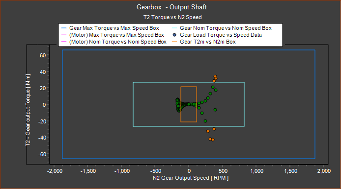 |
Gearbox Torque and Speed Limits. The Show Gearbox Limits check-list box is above the Gearbox selection box. ❑ Show Gearbox Limits OFF The axes are auto-scaled to the Maximum Application Torque and Speed, at the output of the Gearbox. ☑Show Gearbox Limits ON The axes are auto-scaled to the Maximum Torque and Speed Capacity, referred to the output of the Gearbox. This helps you compare the Torque and Speed Capacity of the Gearbox with the Application Load. The Limits of Torque and Speed are shown as boxes. Before you select a servomotor, the limit boxes and their color codes indicate the: •Dark Blue : Maximum Torque and Speed capacity of the Gearbox •Light-Blue : Rated (or Nominal) Torque and Speed capacity of the Gearbox •Light-Brown : Equivalent Torque and Speed of the Application Load |
Select a Servomotor Manufacturer
|
 Note: If you need us to list a different Servomotor Manufacturer, then please email us. |
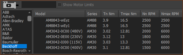
Select a Servomotor Model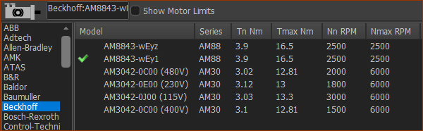 When you select a Servomotor Manufacturer, and Auto-Filter is ON, and you have entered a Range-Factor, the list of Servomotor is limited to those whose capacity can satisfy these in-equalities: |
||||||||||||||||||||||||||||||||||||||||
|
||||||||||||||||||||||||||||||||||||||||
d1max≤ D ≤ d1min The Servomotor Shaft Diameter, D, must fit directly into the Gearbox, d1. Note: Most Precision Planetary Gearboxes can accept a range of shaft diameters at their input. The Gearbox inertia is referred to the input shaft, and is different for each shaft diameter. Tmax ≤ Tmotmax ≤ RF × Tmax Maximum Application Load Torque referred to the Gearbox input-shaft ≤ Maximum Servomotor Torque Capacity ≤ Range-Factor × Maximum Application Load Torque referred to the Gearbox input shaft Tm ≤ TN ≤ RF × Tm Equivalent Application (Load) Torque referred to the Gearbox input-shaft ≤ Rated Servomotor Torque Capacity ≤ Range-Factor × Equivalent Application (Load) Torque referred to the Gearbox input shaft Tmax ≤ Tmotmax ≤ RF × Tmax Maximum Application (Load) Torque referred to the Gearbox input-shaft ≤ Rated Servomotor Torque Capacity ≤ Range-Factor × Equivalent Application (Load) Torque referred to the Gearbox input shaft n1max ≤ Nmax Maximum Application Speed referred to the Gearbox input-shaft ≤ Maximum Servomotor Speed nN ≤ NN Average Application (Load) Speed (or Equivalent, Mean) ≤ Rated Servomotor Speed |
||||||||||||||||||||||||||||||||||||||||
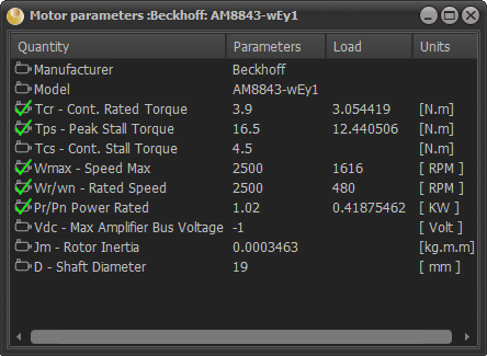 |
When you select a Gearbox model, its Gearbox Parameters Summary Sheet will show. This form is read only. There should be 4 × Peak Servomotor Torque ≥ Maximum Application (Load) ÷ i Rated Servomotor Torque ≥ Equivalent Application (Load) Torque ÷ i Max Servomotor Speed ≥ Maximum Application (Load) Speed × i Continuous Servomotor Speed ≥ Equivalent Application (Load) Speed × i Rated Power > Nominal Load Power. Other Parameters include: •Vdc - Bus Voltage for Drive •Jm - Servomotor Inertia •D - Servomotor shaft diameters. |
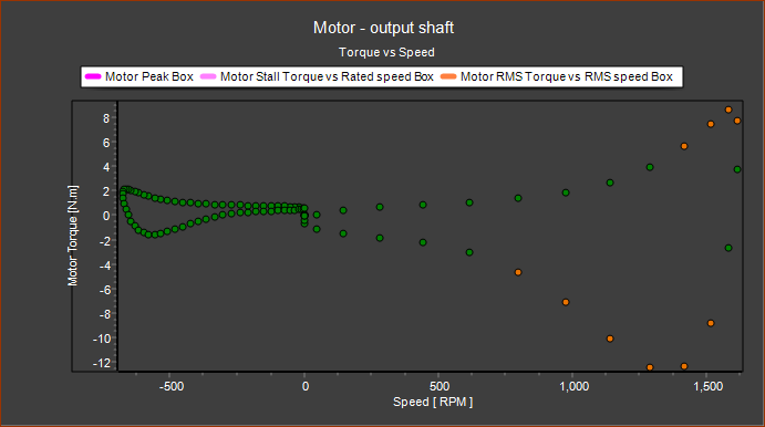 |
When you select a Gearbox, colors of the dots for the Torque (N.m.) vs Speed (RPM) plot changes to indicate whether the Gearbox has the Capacity to drive the Application Load or not. The color code is : •Green : Torque AND Speed of the Load ≤ Rated Servomotor Capacity •Amber : Torque OR Speed of the Load ≥ Rated Servomotor Capacity ≤ Maximum Servomotor Capacity •Red : Torque OR Speed of the Load ≥ Maximum Servomotor Capacity |
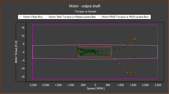 |
Motor Torque and Speed Limits. The Show Motor Limits check-list box is above the Motor selection box. ❑ Show Motor Limits OFF The axes are auto-scaled to the Maximum Torque and Speed, at the Servomotor Drive Shaft. ☑Show Motor Limits ON The axes are auto-scaled to the Maximum Torque and Speed Capacity of the Selected Servomotor This helps you compare the Torque and Speed Capacity of the Servomotor with the Application Load referred to its input-shaft. The Limits of Torque and Speed are shown as boxes. • Purple : Maximum Torque and Speed capacity of the Servomotor • Pink : Rated (or Nominal) Torque and Speed capacity of the Servomotor •Light-Brown : Equivalent Torque and Speed of the Application Load |
The Torque we show in the graphics-area when we use Force toolbar >Display Force Vectors is the torque to move the mechanism only. It does not include the Torque to move the motor and gearbox. It is necessary to add the Torque to accelerate the motor and the gearbox to Torque in the graphics-area. Clearly, the Torque to move motor depends on the ....inertia of the motor and gearbox as well as the gearbox ratio. The higher the gear ratio, the less Torque the motor 'sees'. But the motor must run faster and accelerate more. This influences the overall power, as well as system efficiency. |
The performance characteristics of a brushless servo motor (motor/drive combination) are described by a torque/speed operating envelope. As shown below, the colored areas of the curve identify the Exceeded Duty, Continuous Duty and Intermittent Duty zones of the system. Exceeded Duty To move the mechanical system, the gearbox and itself, the servomotor must exceeds its maximum speed or the maximum torque, or both. Continuous Duty Zone (S1) The continuous duty zone is bordered by the maximum continuous stall torque up to the intersection with the intermittent duty line. The continuous torque line is set by either the motor’s maximum rated temperature, or the drive's rated continuous current output, whichever is less. The system maximum continuous or 'voltage line' is set by the voltage rating of the drives, the line voltage supplied, and the motor winding. The system can operate on a continuous basis anywhere within this area, assuming the ambient temperature is 40°C or less. Intermittent Duty Zone (S5) The intermittent duty zone is bordered by the peak stall torque and the system voltage line. The peak torque line is set by either the drives’ peak current rating, which the drive can give for a limited time, or the maximum rated peak current for the motor, whichever is less. Higher torque levels may be achievable at higher power levels. |
|
 Typical Torque / Speed Duty Capability of a Brushless Servomotor. |
Peak Torque: (ԎPS ) The Peak Torque the Motor and Gearbox at Stall Speed Continuous Stall Torque: (ԎCS ). The Continuous Torque the Motor and Gearbox can give Continuously at Stall Speed. Maximum Speed: (ωMAX ) Maximum possible speed of the Motor and Gearbox. Not attainable when the voltage is limited by the drive. Knee Speed: (ωK ) The Speed at 'knee' in peak envelope that is the intersection of the Peak Torque with the Voltage Torque/Speed Limit Line. Motor Providers also give a Rated Power - this is dependent on the Drive. Continuous Rated Torque:(ԎCR ). The Continuous Torque at the Speed of the Rated Power. Rated Speed: (ωR ) The Rated Speed or Speed at Rated Power. The motor can operate at this speed with the supply voltage. |
The Reflected Inertia at the Motor shaft usually continuously changes in a machine-cycle. With Constant Inertia, Friction, Speed Mechanical Systems it is easy to calculate Inertia Torque. With mechanisms, the Torque Load is a function of Acceleration, Velocity, and Position. PSMotion has developed algorithms to calculate these, which give a true indication of the reflected inertia at a motor shaft for even the most complex mechanisms. The equations below, are calculated at every instant in a machine-cycle. Typically, you aim to make the Reflected Load Inertia = (Motor + Gearbox) Inertia. However, when the Load Inertia is not constant, it is more difficult to select the Motor and Gearbox. |
|
Speed: ωm = N × ωL αm = N . αL Torque Tm = - αm (JG + JM) + sign(TVD) TL = (TMD ∕ N ) ∕ η TT = Tm + TL |
N = Gear Ratio ωm = Motor Angular Velocity ωL = Load Angular Velocity TT = Total Torque Tm = Motor Torque TL = Load referred to Motor Shaft TVD = Viscous 'Drag' Torque. It is always opposite to the direction of motion TMD = Torque derived by MechDesigner at Motor Shaft ( f{PL , ωL, αL } ) JG = Inertia of Gearbox JM = Inertia of Motor αm = Motor Acceleration αL = Load Acceleration η = Gearbox Efficiency |