Does the SOLIDWORKS Model agree with the MechDesigner Model?
3D-Cams have complex surface geometry. If you want to manufacture a Globoidal Cam, we recommend that you make sure the MechDesigner model and the 3D-Cam in SOLIDWORKS® agree. In other words, if you give a Radial Clearance of 0.005mm (see 3D-Cam dialog) in MechDesigner, the SOLIDWORKS® model should agree with this clearance throughout the indexing and dwell motion. This tutorial uses the CAD-Control FB to move an assembly model in SolidWorks (you must prepare this), to the same as position as the MechDesigner model. Then you can use the Clearance Detection tool in SolidWorks to see whether the Flank-Clearance' Parameter, as set in the MechDesigner model, agrees with the clearance as found in the SolidWorks model. If the communications with the CAD-Control FB fails, enter the two 'angle mates' (see below) manually in SOLIDWORKS. |
|
|
Add the CAD Control FB to the graphics-area: 1.Click Modeling-FB toolbar > CAD Control FB 2.Click again in the graphics-area The CAD Control FB is now in the graphics-area. |
Use the CAD Control FB to synchronize the positions of SOLIDWORKS® Parts that are a SOLIDWORKS® Assembly model with the Parts in a MechDesigner model. Q: Why do this when MechDesigner is perfect to model motions? A: Because SOLIDWORKS® has other useful tools that include: •Collision Verification •Interference Detection. The Clearance Detection Tool in SOLIDWORKS calculates the exact gap between Parts. We connect motion-values from Function-Blocks that move the indexer to the CAD Control FB. When you configure the CAD Control dialog, Distance or Angle Mates in SOLIDWORKS® are driven by motion-values in the MechDesigner indexer model. The motion of the SOLIDWORKS® model is then same as the MechDesigner model. But, do not use Cycle in MechDesigner as the communication between the programs is not fast enough. |
|
 Model Preparations in SOLIDWORKS® and MechDesigner
|
1.MECHDESIGNER MODEL This model is the CamCo® Part Number M601RDM4H24-330 in (weblink) CamCo catalog, Page B-4. •A Globoidal Cam. •4-Stop Cam, with 12 Follower-Rollers. •Index motion: 'Modified Sine' but with 33% Constant Velocity – MSC33. •Index-Period is 330º, Dwell-Period is 30º. •Distance between the input and output shafts is 107.95mm (4.25"). There are two motions: •The rotation of the 3D-Cam – constant angular velocity •The rotation of the Follower Wheel – the index motion |
|
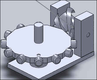
2.SOLIDWORKS® EQUIVALENT ASSEMBLY MODEL •We have transferred the 3D-Cams and the Cam-Blank to SOLIDWORKS® from MechDesigner to make the Globoidal Cam Part. In SOLIDWORKS®, we have: •Modeled a 'frame' to represent the Cam-Box and the two orthogonal axes. •Modeled an equivalent Follower Turret (or 'Wheel') •Modeled the axes of rotation of a Cam-Box •Assembled the three Parts: Frame, Follower and Cam-Part (from MechDesigner). Clearly, the Cam-Box and Follower Turret/Wheel are simplified. However, they are configured in the same way as the Cam-Box in the catalog. The 'Front' Plane of the 3D-Cam should be the 'Front' Plane in SolidWorks®. |
|
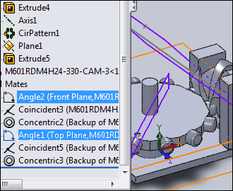
3.SOLIDWORKS® 'MATES' Here, we add mates (SolidWorks® terminology) that we want to control with motion-values from the MechDesigner model. The mates in the SolidWorks model are (see image): 1.Mate 1: ANGLE2 is between a Fixed and a Moving Plane in the 3D-Cam. The 3D-Cam rotates when we edit the value of Angle2. 2.Mate 2: ANGLE1 is between a Fixed and a Moving Plane in the Follower Turret. The Follower Turret rotates when we edit the value of ANGLE1. The two mates in the Feature Tree, are in the image to the left. The Cad Control Function-Blocks drive the mates Angle 2 and Angle1 . You can rename Mates in SolidWorks. |
|
Notes on Angle Mates in SOLIDWORKS: Angle mates in SOLIDWORKS® can not be negative. They have a range from 0º to 360º'. The output from an Motion-Dimension (Rocker) in MechDesigner has a possible range of -180º to 180º. Much larger if we select the Accrue Index Motion check-box in the Motion FB dialog. The Positive and Negative directions of the Mate should be the same in SOLIDWORKS® and MechDesigner. You should test which is positive direction with the Angle Mate control in SOLIDWORKS. |
 Cams in MechDesigner")
Prepare the Motions in MechDesigner
|
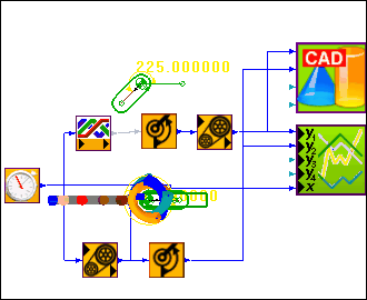
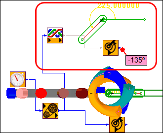
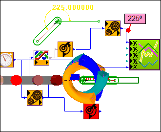
The motion of the 3D-Cam (Input Shaft) and the motion of the Follower (Output Shaft) are in different Mechanism-Editors. We must make them available in one Mechanism-Editor. We must add an indexing Follower Part in the Cam-Shaft Editor In the image to the left Show Solids in Mechanism is Toggled IN'), the Part and the Function-Blocks in the 'Red Rectangle' have been added. Note: Even though the Motion-Dimension value is 225º, the output value from the Angle Motion-Dimension FB itself is -135º! As you cycle the Model in MechDesigner, the -135º value increases in the Positive sense to 0º and up to 225º. |
|
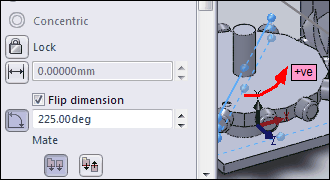
The Angle Mate in SOLIDWORKS® is '+225º'. Note: It is not possible to make angle negative in SOLIDWORKS®, thus we add 360 to –135º' to give 225º We have configured the angle mate to increase in the same positive sense. To do this we: •Add a Gearing FB, and edit the Add to Output parameter to 360º. •Connect the Gearing FB to the Motion-Dimension FB. •Add a Graph FB to help make sure the motions values that you want to connect to the Cad-Control FB input-connectors will agree with the required changes to the Angle Mate parameter in SolidWorks®. |
Add the CAD Control and compare data
|
STEP 1: Open SOLIDWORKS STEP 2: In MechDesigner, Add a Cad Control FB to the graphics-area STEP 3: Connect FBs with the correct motion-values to the Cad Control FB to control the Angle Mates in SOLIDWORKS. STEP 4: Double-Click the Cad Control FB to configure it.
|
|
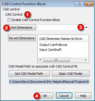
With the SOLIDWORKS model open: STEP 1: Select the Enable CAD Control Function-Block option. STEP 2: Click Get Dimensions The dialog, 'finds' the correct mates in SOLIDWORKS. STEP 3: Click the Get Dimension list, to see the Mates found in SOLIDWORKS. STEP 4: Select the SOLIDWORKS Mates, top to bottom, that agree with the Motions, top to bottom, at the input-connectors of the CAD Control FB. Note: I renamed the mates in SOLIDWORKS from Angle2 and Angle1 to 'Output CamFollower' and 'Input CamShaft'. STEP 5: Click OK Now, the positions of the Parts in SOLIDWORKS move when you move the Parts in MechDesigner. |
|
The connection is slow – say a step per second. Use the 'Step Forward', 'Step Backwards' or the 'Home' buttons – DO NOT USE THE CYCLE buttons. |
|
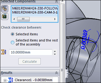
It is possible to use the 'Interference Detection' and 'Clearance Verification' tools in SOLIDWORKS®. STEP 1: Change the 'Units' in the 'Document Properties' of the 'Options' in SOLIDWORKS to mm with 6 decimal places STEP 2: 'Step Forward' the cam-shaft in MechDesigner to, say, 18º, as indicated in the Master-Machine-Angle The Follower moves to the angular position given by the Modified-Sine Motion-Law, with Constant-Velocity of 33%, in the MechDesigner and SOLIDWORKS models. (If this does not happen the communication between MechDesigner and SOLIDWORKS has not worked. Do not worry. Manually enter the angles in SOLIDWORKS. You must read the two angles in MechDesigner and manually set the angles in SOLIDWORKS STEP 3: In SOLIDWORKS, use the Clearance Verification Tool STEP 4: Click the Follower Turret and the 3D-Cam The SOLIDWORKS Clearance Validation Tool calculate the clearance as 0.00389mm. I typically put 5μm (0.005mm) clearance between the Follower and the 3D-Cam in the 3D-Cam dialog – dependent on the 3D-Cam or Follower Size. This means the data sent to SOLIDWORKS: •Was calculated correctly in MechDesigner to less than 1.111μm, and / or •SOLIDWORKS gives the surface derived from the 3D-Cam 'Rims' to less than 1.111μm. |