Add Solids
Note: In Step 15.4, we added two Parts which we joined to the Piggyback-Sliders with Pin-Joints. Also, we added a Slide-Joint between the CAD-Lines in the two Parts. The Parts and Joints assemble as an R-P-R dyad. One of the Parts in the R-P-R dyad has been renamed to Tool-Part.
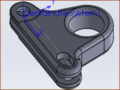
We will design a Solid for the Chain-Link. The design combines the Tool and the chain-link. There are two types of Solid you can add to a Part. •Add sketch-loops to represent the shape of a Tool-Part. Then add Profile/Extrusion elements. We call this an MD-Solid. •Import a SOLIDWORKS® part or assembly document onto a CAD-Line. We call this a CAD-Solid. |
You can also:
Import a DXF File and convert DXF Lines or Circles to MechDesigner sketch-elements - see Tutorial 8 Edit a CAD-Line to import an STL file from other CAD. |
Use the two methods to add Solids to a Part
|
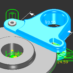
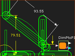
STEP 1: Add a Measurement FB between the Pin-Joints
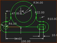
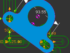
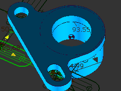
The distance between the Pin-Joints in the R-P-R dyad changes •from a maximum of 100mm when the Parts move between the sprockets. •to a minimum of 93.55mm when the Parts move around the sprockets. Thus, we must add a slot to the Tool for Chain-Links range in length. This image is the sketch of the Tool. There is a short slot at the right side of the Tool that is 10mm long. |
|
|
||
|
Now the shape of the Extrusion is complete:
|
|
|
Here, I have also added:
|
SolidWorks® documents can have much more design detail. You can: 1.Import the complete SolidWorks® Assembly document onto one CAD-Line. or 1.Use the Part-Editor to add more CAD-Lines to a Part 2.Import different SolidWorks® documents onto different CAD-Lines. |
||
|
|
|
|
||
|
|
|