Simple Gear Trains
 Schematic of Simple Gear Train |
A Simple Gear-Train has two or more Gear-Pairs that you connect in series. The Driven-Gear of one Gear-Pair becomes the Driving-Gear of the next Gear-Pair in the series, and so on in the series. Use a Simple Gear-Train to: •increase the distance between the input and output shafts and still use small gears •reverse the direction of the output shaft on a Simple Gear-Pair •increase or decrease the Torque and Speed at the output-shaft. The image to the left is a schematic of a Simple Gear Train. Note: 1.The Driving-Gear on the first Gear-Pair and the Driven-Gear or the last Gear-Pair in the series of gears control the gear and speed ratio. 2.All other gears are idle gears or idlers - they do not affect the overall Gear-Ratio. |
 Schematic of a Monobloc machine. |
Application of Simple Gear-Train - a Monobloc Machine Monobloc machines include Filling, Capping, Labeling, Coding, Orientating and many other high-speed applications. The Monobloc uses a simple gear-train to transmit the motion from shaft to shaft. See YouTube Video: http://youtu.be/fvRp2lC1aXw
|
Gear-Pair 1
 Gear-Pair with Fixed Centers |
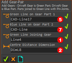
Add a Gear-Pair
|
|
Gear Ratio is Z1/Z2 = 2 ; Distance between Gear Axes = 60mm |
||
Gear-Pair 2 : PREPARATION
 in Part-1(4)") Line-1(5) in Part-1(4) |
Line 1 in Part 1 : The Driven-Gear of Gear-Pair 1 will be the Driving-Gear of the Gear-Pair 2.
|
|
 Line 2 in Part-2 Before you do Merge-Points |
Line 2 in Part 2 (the Base-Part)
|
|
") Line 3 in Part 3 (new Part) |
Line 3 in Part 3 : A new Part - it will be the Driven-Gear.
|
Gear-Pair 2 : ADD GEAR-PAIR
|
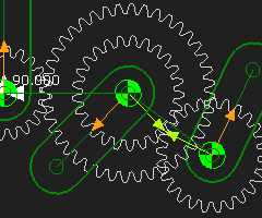
You can now add Gear-Pair 2
|
|
|
You can see the Gear-Pair 2
|
|
|
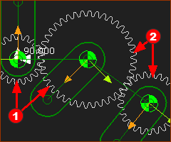
Use the Gear-Pair dialog to edit:
The image is Gear-Pair The position of Gear 2 of Gear-Pair |