Design Checklist with the Cam-Data FB
|
Add a Cam-Data FB ... edit the FB and link the Cam-Data FB to a 2D-Cam, close the dialog. ... use a Graph FB to plot the data available at the output-connectors from the Cam-Data FB to check 2D-Cam design parameters. See Add Cam-Data FB and Edit Cam-Data FB |

In MechDesigner, we do not stop you adding a cam that will be difficult to operate, and will have a short life-time and may induce vibrations in other mechanical components.
Whether a cam is Good or Bad is a function of its capacity to perform its duty for a specified life.
To find out whether the Cam is Good or Bad, we can do:
•Geometric Analysis
•Force and Stress Analysis
Geometric Analysis:
The Geometric Analysis reviews the:
•Cam Size
The cam's size, pressure-angle, and radius-of-curvature are related to each other. They are a function of the geometric layout of the cam mechanism, given a motion. It is critical that you review these parameters early in your cam design. They strongly influence the contact force and contact stress.
Force Analysis:
Before you analyze Contact-Force and Contact-Stress, the power must flow from a Power-Source to the Tool-Part, via the Cam and Follower. You must Configure the Power Source to make sure that the Power flows correctly. See: Configure the Power Source for Payload Analysis |
The Force Analysis reviews the:
•Contact-Force - which we use to find the Life of the Follower-Roller.
•Contact-Stress (Hertzian Stress) - which we use to find the Life of the Cam-Profile.
Generic Payload Types and 'Signatures'
Payload: is the superposition (addition) of the different payloads that act on the Follower - the total load of the output transmission. Payload Signature: is how the payload varies over one machine cycle. Payload Type: are a function of the motion-derivative, and thus, they are a function of machine-angle and machine-speed. Payload Signatures vs Motion-Derivative |
||
|---|---|---|
Payload Signatures |
Motion-derivative and Payload Type |
Examples |
|
Not a function of the motion Constant Load |
Gravity, 'Friction', Spring Pre-load |
|
First Motion-Derivative Load Proportional to Displacement |
Spring Displacement |
|
Second Motion-Derivative Load Proportional to Velocity |
Viscosity, Air-Cylinder |
|
Third Motion Derivative Load Proportional to Acceleration |
Inertia Forces |
|
A different function of Machine Angle, for example an engine's piston load. |
'Power' stroke of an Engine |
Importance of Machine Speed
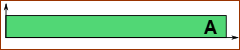
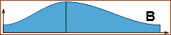
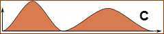
In the example below, the payload is the superposition of three load types: •Constant Force (Green), for example: Gravity, Air-Cylinder. •Displacement Force (Blue), for example: Spring Force. •Acceleration Force (Magenta), for example: Inertia Force. |
|
|---|---|
 Cam forces at 'Low Speed'. |
Low Machine Speed: •The maximum payload is at the maximum displacement of the cam •The acceleration force is low. |
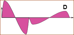
 Cam loads at 'High Speed'. |
High Machine Speed: •Accelerations increase to machine speed squared. •The maximum payload is during the motion 'rise' •The minimum payload is also during the motion 'rise', but during the negative acceleration phase. The minimum force is less than 0N |
Follower: Payload 'Signature'
 Cam-Follower: Payload Signature of 'Force-Closed Cam'.
In this example, the Follower Roller is 'active' for the complete machine cycle. |
First: review whether the contact-force is active against the cam for the complete machine cycle or only part of the machine cycle. The Contact-Force Signature maybe different for a Force-Close Cam when compared to a Body-Closed Cam. Body Closed Cam - Conjugate-Cam types •Follower-Roller is active during the acceleration phase of the 'Rise', and the deceleration phase of the 'Return'. •Follower-Roller is active for the other phases. Body Closed Cam - Type 2: Groove-Cam types •One Follower-Roller is active for the complete machine cycle. •The other Follower-Roller is in contact with one cam-profile as the follower accelerates and the other cam-flank as it decelerates. •The roller must reverse its rolling direction when it changes cam-flanks. As it changes rolling direction, it must scuff when the linear speed of the roller-surface and speed of the cam-flank are not equal. •The contact force is zero (0) while the roller moves between flanks within the backlash zone. There must be some backlash with Groove-Cam types. Force-Closed Cam •The roller is 'active' for the complete machine cycle, assuming the Contact-Force does not become ≤ 0N. |
Cam: Payload 'Signature'
/2; Stress Amplitude = (Max-Min)/2; Max Stress = 2*Mean, Minimum Stress = 0 MPa") CAM-STRESS: Mean-Stress = (Max+Min)/2; Stress Amplitude = (Max-Min)/2; Max Stress = 2*Mean, Minimum Stress = 0 MPa Mean-Stress = (Max+Min)/2; Stress Amplitude = (Max-Min)/2; Max Stress = 2*Mean; Minimum Stress = 0 MPa |
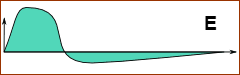
Each point along the cam surface (and just below) becomes stressed at one 'machine angle'* in the machine-cycle The stress that the point experiences is zero at all other machine angles. For each point along the cam, the stress is said to pulse (like heart-beat pulses) with a 'period' of 2.π or 360º. Assumes the cam rotates one time per machine cycle. This image shows the 'stress pulse' at a single position on the cam's surface
|