3D-Cam
See also: 3D-Cam dialog
Add 3D-Cam does NOT remove a degree-of-freedom from the model. We calculate for you the shape of a 3D-Cam from the relative motions of a Cam-Part and Follower-Part, together with the shape of the Follower-Profile. You must also add the shape of a Cam-Blank and its rotating-axis. The elements are in 3 or 4 different Mechanism-Editors. We recommend you do |
Terminology
3D-Cam : |
A 3D-Cam has complex and twisting Cam-Surfaces (Cam-Flanks) that interact with Follower-Rollers. The rotating-axis of the Cam-Part is not parallel with the rotating-axis of the Follower-Part. |
There are many variants of a 3D-Cam. Barrel, Cylindrical, and Globoidal Cams are different types of 3D-Cams. Globoidal Cams are also known as Roller-Gear-Drives and Ferguson Cams. There are also Face, Groove, and Rib types. The Cam-Part, or the Follower-Part, can be stationary. or rotate with a constant, or a non-constant angular-velocity. |
|
Prepare for Add 3D-Cam (typical)
All Parts are kinematically-defined before you do Add 3D-Cam. You must select 5 elements, from 3 or 4 Mechanism-Editors. |
|||
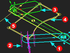 |
The five elements are:
|
||
To see the five elements in the graphics-area: |
|||
|
•Visibility toolbar (or menu) > Show other Kinematic and Sketch elements |
||
|
AND •Right-click the Mechanism name-tab of each Mechanism-Editor and click Show with 'other Kinematic and Sketch elements'. |
||
|
AND •View toolbar > Spin, or use your arrow keys on your keyboard, to spin the model to see the 5 elements in the 3 or 4 Mechanism-Editors. |
||
|
It is also easier if you hide Solids: Deselect : Visibility toolbar (or menu) > Show Solids in Mechanisms |
||
Add 3D Cam
 |
STEP 1: Click Add 3D-Cam
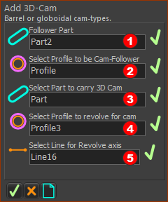
There are five elements to select in the Command-Manager. STEP 2: Click the five elements in the graphics-area or Assembly-Tree.
STEP 3: Complete the command
STEP 4: Edit and save the 3D-Cam
|
|||||
Elements to add a 3D-Cam: |
||||||
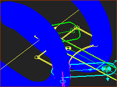 |
Result
|
Video:

Video: Add 3D-Cam