Rack-Pinion / Ball-Screw
See also: Rack-Pinion dialog
Add Rack-Pinion removes ONE degree-of-freedom from the model. Before you do Add Rack/Pinion, the Pinion or the Rack is kinematically-defined. After you do Add Rack/Pinion, the Pinion AND the Rack are kinematically-defined. We calculate for you: •the motion of a Rack from the motion of a Pinion or •the motion of a Pinion from the motion of a Rack |
Terminology
Rack -Pinion : |
A Rack-Pinion is the term for a sliding, straight, linear-gear (Rack) that is in mesh with a rotating, circular, gear-wheel (Pinion). The motions of the two Parts are kinematically related by the module and number-of-teeth on the Pinion. |
Ball-Screw : |
A Ball-Screw is a device in which a screw rotates to move a nut, or vice-versa. The Linear-Motion of the nut and the rotation of the screw are related by the lead of the screw. |
sliding-Part : |
A Part that is joined to a different Part with a Slide-Joint. |
rotating-Part : |
A Part that is joined to a different Part with a Pin-Joint. |
How to prepare for Add Rack-Pinion (typical)
There are two model types.
A: The motion of the Rack is from the motion of a Pinion:
|
Elements before you do Add Rack-Pinion
Line or CAD-Line |
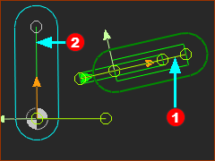
B: The motion of the Pinion is from the motion of a Rack
 |
Elements before you do Add Rack-Pinion
Line or CAD-Line |
Add Rack-Pinion
A: If the motion of the Rack is from the motion of a Pinion
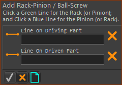 |
STEP 1: Click Add Rack-Pinion
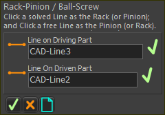
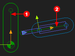
In the Command-Manager, there are two elements to select. STEP 2: Select the two elements in the graphics-area
STEP 3: Complete the Command
Result :
|
|||||
 |
||||||
|
||||||
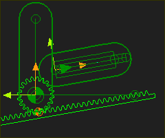 |
B: If the motion of the Pinion is from the motion of a Rack
 |
STEP 1:Add Rack-Pinion
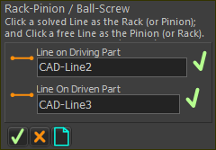
In the Command-Manager, there are two elements to select. STEP 2:Select the two elements in the graphics-area
STEP 3:Complete the Command
The Rack-Pinion is now in the Assembly-Tree and graphics-area. Result :
|
|||||
 |
||||||
|
||||||
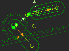 |
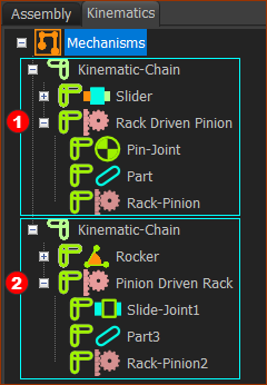
Kinematics-Tree of Rack-Pinion
|
|
|
|
Video of Add Rack-Pinion
Video: Add Rack-Pinion
