 Mechanism-Editor
What is a Mechanism-Editor?
It is a workspace in which you add kinematic and machine elements, and so build your mechanisms (kinematic-chains) for your machine.
There is no limit to the number of Mechanism-Editors you can add.
 Mechanism-Editor- Example |
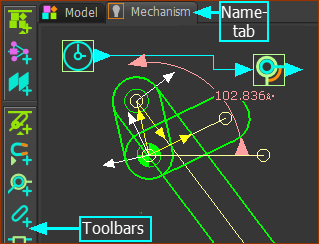
When you do Add Mechanism, you must select a Plane. When the command is complete, we add for you a new: •Mechanism element, which is coplanar with the Plane you select. The Mechanism element provides a Mechanism-Editor workspace. This includes a: •Graphics-area, which is also coplanar with the Plane you select. •Name-tab •XY-axes
|
Why add a Mechanism-Editor?
You use the Mechanism-Editor's workspace to add kinematic and machine elements that build kinematic-chains. You add Function-Blocks to plan the motion of each kinematic-chain. You may add mass and mass moment of inertia to Parts, so that you can analyze the forces in each Part. You spend perhaps 90% of your time modeling your machine in one or Mechanism-Editor. |
Mechanism-Editor workspace
 Mechanism-Editor- Example |
The Mechanism-Editor workspace: Graphics-area : To which you add Kinematic and Machine elements, Kinematic and Modeling Function-Blocks, Solid elements, Force elements, and other elements. Name-tabs : Each Mechanism-Editor you add to a Plane has a Mechanism name tab. Each Mechanism name-tab has a Light-Bulb icon and a Color icon - see Visibility menu > Kinematic-Elements The Base-Part (not shown in the image above) is a child to the Mechanism element. It represents the frame, or the stationary part, of the workspace. The XYZ-axes of the Base-Part and the Plane you select to add the Mechanism-Editor are coincident. |
Menus and Toolbars
The menus and toolbars are:
Mechanism menu - has the commands in the: Model elements toolbar - left of the graphics-area - add Planes and add Mechanism-Editors to Planes Kinematic elements toolbar - left of the graphics-area - add the basic kinematic elements to build kinematic-chains Machine elements toolbar - left of the graphics-area - add more complex elements Function-Blocks menu - has the commands in the: Kinematic Function-Blocks toolbar - right of the graphics-area - plan and measure the motion of each kinematic-chain, analyze and calculate cam-coordinates Modeling Function-Blocks toolbar - above the graphics-area - tools to help you do more complex modeling Forces menu - has the commands in the: Force elements toolbar - right of the graphics-area - measure force, torque, and power that is required to drive each kinematic-chain MD-Solids menu - has the commands in the: MD-Solids toolbar - above the graphics-area - to add Solids as Profiles, extrusions, Holes, ... . |