2D-Cam
See also: 2D-Cam dialog
Add 2D-Cam does NOT remove a degree-of-freedom from the model. We calculate for you the shape of a 2D-Cam from the motions of a Cam-Part and a Follower-Part, together with the shape of the Follower-Profile. Before you can do Add 2D-Cam, you must add the Cam-Part, Follower-Part, and a Follower-Profile to the Follower-Part. They Parts be kinematically-defined. |
Cam Terminology
2D-Cam Work-flow
|
||||||||||||||||||||||||||||||||||||||||||||||||||||||||||||||||||
Prepare to add 2D-Cam (typical):
 A model that is prepared with the minimum number of elements to do "Add 2D-Cam" |
The elements you need in the model before you can do Add 2D-Cam:
See also Follower-Profile Shapes. |
Do Add 2D-Cam:
 Command-Manager: Add 2D-Cam |
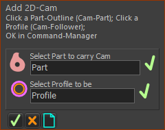
STEP 1: Click Add 2D-Cam
There are two selection-boxes in the command-manager for two elements. |
||||||
|
STEP 2: Select the two elements
Typically, the Follower-Profile is a Follower-Roller or a Flat-Faced Follower.
|
||||||
 |
STEP 3: Complete the Command
It may be necessary to do Rebuild Now - see Quick Access menu
|
||||||
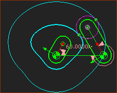 |
Result : Graphics-area
|
||||||
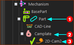 |
Result : Assembly-Tree
|
||||||
The icon for the 2D-Cam element in the Assembly-Tree may warn you that it is a “Bad Cam”.
|
|||||||
Next Steps: see 2D-Cam Work-Flow.
Video (EN):

Video: Add 2D-Cam