When should I use a CAD Control FB?
Use a CAD Control FB to synchronize the motion of one or more parts that are in a SolidWorks® Assembly with the motion of same Parts in a MechDesigner model/assembly. Question: Why do this when MechDesigner is perfect to synchronize the motions of all of the Parts in a model? Answer: Because SolidWorks® has useful tools. For example, Collision Verification, Interference Detection, ... The Clearance Detection tool in SolidWorks® evaluates the exact gap between parts. You can use this tool to check that a 3D-Cam you export to SolidWorks has the same Clearance as the Radial Clearance that you enter in the 3D-Cam dialog. After you configure the CAD Control dialog, motion-data that controls Parts in MechDesigner model/assembly are piped to the SolidWorks Distance or Angle mates that define the position of a Part in the assembly in SolidWorks®. |
See also: CAD Control dialog
Add CAD Control FB
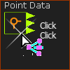
STEP 1Add a CAD-Control FB to the graphic-data
The CAD-Control FB is in the graphics-area. STEP 2: Open the CAD-Control dialog:
The CAD-Control dialog is now open. STEP 3: See CAD Control dialog |
||||||
Note: Angle mates in SolidWorks® cannot be negative, but they can be in MechDesigner. Thus, you may need to use Gearing FBs to add a constant to the output values so that they have the same minimum and maximum values as those in SolidWorks®. |
||||||