CAD Control FB
see Add CAD-Control FB.
|
Use a CAD Control FB to synchronize Distance or Angle mates in a SolidWorks® assembly document with the motion of Parts in a MechDesigner model. You can control up to four(4) SolidWorks® mates with one CAD-Control FB. Why use a CAD-Control FB? You can use the powerful Evaluation / Validation Tools in SolidWorks® to check the clearance between a Follower-Roller and the flanks of a 3D-Cam, for example. Note the SolidWorks® mates respond very slowly. Increment the model very slowly when you using the CAD-Control FB. See Getting Started Tutorial 6C3: Examine 3D-Cam Clearances |
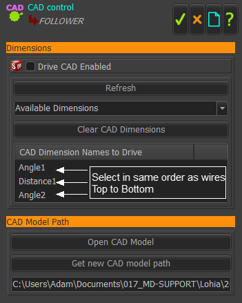
 CAD-Control dialog |
|
STEP 1: Connect wires to the input-connectors of the CAD-Control FB from other FBs in your model. The motion-values at the output of a FB you connect should control a Motion-Dimension - it will control a Distance or Angle Mate in SolidWorks. To control a Distance (or Angle) Mate, set the Output Data Type in each Motion FB dialog to Linear (or Rotary). STEP 2: Open the SolidWorks Assembly. STEP 3: Double-Click a CAD-Control FB in MechDesigner If necessary, click Dimensions and CAD Model Path to expand the dialog. STEP 4: Click the Refresh button. When you click the Refresh button, we find for you all of the Dimension and Angle mates in your SolidWorks® Assembly model. STEP 5: Click the Available Dimensions down-arrow button to see the mates that we have found in the SolidWorks® Assembly model. STEP 6: Click, in the Available Dimension list, each Dimension or Angle mate you want to control. Repeat to select and control a maximum of 4 mates - for 4 input-connectors and wires (see STEP 1) Note: Select the mates in the same order (sequence) as the wires Mate1 = Wire 1(top); Mate 2 = Wire 2; Mate 3 = Wire 3; Mate 4 = Wire 4(bottom). The mates show in the CAD-Dimension Names to Drive box. If the mates are not in the same sequence as the wires you can click the Clear CAD Dimensions button. You can select the mates again. STEP 7: Click the Drive CAD Enabled check-box at the top of the dialog. DO NOT CLOSE THE DIALOG You can only control the mates with this dialog open. The position of the parts in the SolidWorks® Assembly model move* when you move your model in MechDesigner. STEP 8: Click * Only use the Home, Step Back or Step-Forward buttons in the Run toolbar. Do not use the Cycle button. |
|