Rack-Pinion / Ball-Screw
See: Add Rack-Pinion
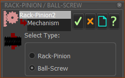
After you add a Rack-Pinion element, you can use the Rack-Pinion dialog to change it to a Ball-Screw and Nut.
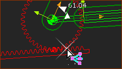
•A Pinion is a gear-wheel with teeth that engage with a linear-gear, or Rack.
•A Ball-Screw is a shaft with threads that engage with a Nut.
In the Rack and Pinion configuration, the motion of the Pinion (or Rack) controls the motion of the Rack (or Pinion).
Or, in the Ball-Screw and Nut configuration, the motion of the Ball-Screw (or Nut) controls the motion of the Nut (or Ball-Screw).
Use the Rack-Pinion dialog to edit the parameters for the Rack and Pinion (Module, number-of-teeth, ...), or Ball-Screw (Pitch, Diameter, ...).
 |
After you add a Rack-Pinion, you will need to edit its parameters - see Add Rack-Pinion. To edit the Rack-Pinion:
The Rack-Pinion dialog is now open. |
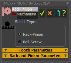
Rack-Pinion / Ball-Screw dialog
 Rack-Pinion / Ball-Screw dialog |
The format of the Rack-Pinion dialog changes when you enable: •Rack-Pinion (default) OR •Ball-Screw |
Rack-Pinion enabled:
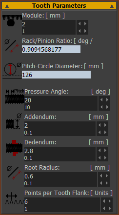 |
Module = P.C.D. ÷ Number-of-Teeth on Pinion |
Rack/Pinion Ratio (degrees), per Rack Displacement (mm). |
|
Read-only: Rack/Pinion Ratio (deg/mm) - number of degrees the Pinion must rotate to move the Rack by 1mm. Pitch Circle Diameter (mm) - the effective diameter of the Pitch Circle of the Pinion. The abbreviation is P.C.D. P.C.D. (mm) = Number-of-Teeth × Module |
|
Pressure Angle (Default = 20º). The Pressure Angle of gears is usually 20º. Other standard Pressure-Angles are: 14º, 17.5º (weaker, quieter), and 22.5º, 25º (stronger, noisier). |
|
Addendum (Usually = Module). The height of the gear tooth from the Pitch-Circle to the tip of the tooth. |
|
Dedendum (Usually = Module × 1.25 (Module>1)). The depth of the gear tooth below the Pitch-Circle to the root of the tooth. The Dedendum is larger than the Addendum to give clearance for the tooth-tip of the two gears that engage with each other. |
|
Root Radius (Usually = 0.3 × Module) The small fillet between the Flank and the Root of the Gear Tooth. |
|
Points per Tooth Flank The number of points on each Involute of each gear tooth. 6 is OK. More points make your model slower to edit. |
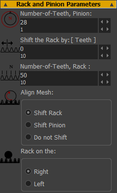 |
Number-of-Teeth, Pinion: The number-of-teeth on the Pinion. As you increase the number-of-teeth, the PCD increase, unless you also edit the Module. Shift the Rack by: Move the rack along its pitch-line by # number-of-teeth. Number-of-Teeth, Rack: The number-of-teeth on the Rack. Edit the Number-of-Teeth on the Rack so that it stays in mesh with the Pinion for a machine-cycle Align Mesh: When you add two(2) Racks to one(1) Pinion, you usually see two(2) Pinions on the same axis. If you want to see one(1) Pinion, click one of these options: ◉Shift Rack ◉Shift Pinion ◉Do not Shift Rack on the: The positive-direction of Rack-Pinion and Ball-Screw model are specified when you select Right or Left. ◉Right (default) When the Pinion (Ball-Screw Shaft) rotates Counter-Clockwise, the Rack (Ball-Screw Nut) move in the Positive-Direction of the Slide-Joint. ◉Left When the Pinion (Ball-Screw Shaft) rotates Clockwise, the Rack (Ball-Screw Nut) move in the Negative-Direction of the Slide-Joint. |
Ball-Screw enabled :
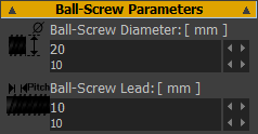 |
The symbol in the graphics-area for a Ball-Screw is a Helix/Screw. There are two parameters: •Ball-Screw Lead (mm) - distance the Sliding-Part moves after one(1) rotation of the Rotating-Part. •Ball-Screw Diameter (mm) - diameter of the Ball-Screw symbol in the graphics-area. The length of the Ball-Screw is equal to the length of the Line in the sliding-Part - see Add Rack-Pinion. The Nut (Sliding-Part) of the Ball-Screw moves in the Positive-Direction of the Slide-Joint when the Rack-Side is set to Right - see General tab |