Gear-Pair
See also: Gear-Pair dialog, Add Bevel Gear-Pair
Add Gear-Pair removes ONE degree-of-freedom from the model. Before you do Add Gear-Pair : •the Driving-Part, which will be the input Pinion, is kinematically-defined. •the Driven-Part, which will be the output WHEEL, is Not kinematically-defined. After you do Add Rack/Pinion, •the Driving-Part AND the Driven-Part are kinematically-defined. •we add a Gear to the Driving-Part •we add a Gear to the Driven-Part |
Gear Terminology
Term : |
Definition |
|---|---|
Gear-Wheel (or Gear) : |
A rotating-Part with gear-teeth at a fixed radius from the rotating axis. You control the diameter of the Gear-Wheel with the number-of-teeth and the module. |
Gear-Pair : |
Two inter-locking gear-wheels. Their gear-teeth have External and/or Internal mesh. The angular velocity of each gear-wheel is related by the Number-of-Teeth on each gear-wheel, and the type of mesh (Internal Mesh or External mesh). |
Driving Part : |
The rotating-Part that is kinematically-defined, and whose motion you control (even if it is stationary) before you do Add Gear-Pair. |
Driven Part : |
The rotating-Part whose motion you control by the motion of the Driven-Part, the Number-of-Teeth on each gear-wheel in the Gear-Pair, and the Mesh. |
Gear-Mesh (or Mesh) : |
How gear-teeth inter-lock with each other so that the Gear-Pair can transmit torque and motion from the Driving Part to the Driven Part. |
External Mesh : |
The gear-teeth of the two gear-wheels point outwards from their centers-of-rotation. |
Internal Mesh : |
The gear-teeth of one gear-wheel point inwards towards its center-of-rotation. |
Simple Gear-Pair : |
Two gear-wheels that rotate about two fixed centers. |
Epicyclic Gear-Pair : |
One gear-wheel orbits around the center of the other gear-wheel. |
Prepare to Add Gear-Pair
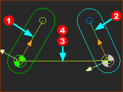
A : Simple Gear-Pair
|
3 × Parts ; 3 × Lines ; 2 × Pin-Joints
|
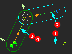
B : Epicyclic Gear-Pair
|
3 × Parts ; 3 × Lines ; 2 × Pin-Joints
|
Add Gear-Pair
A : Simple Gear-Pair
|
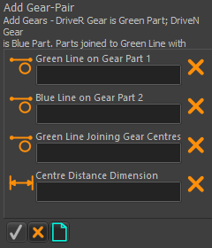
STEP 1: Click Add Gear-Pair (Simple)
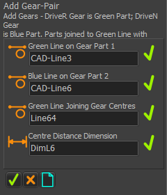
There are four elements to select in the Command-Manager
|
||
|
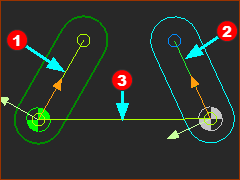
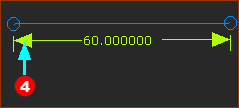
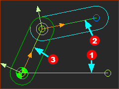
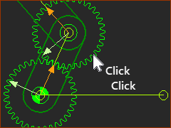
STEP 2: Select the four elements
|
||
|
STEP 2: continued... The Part-Editor opens automatically.
The Part-Editor closes automatically. |
||
|
STEP 3: Complete the Command
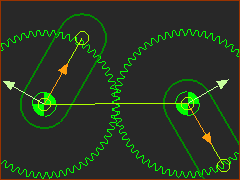
Result:
To edit the Gear-Pair parameters: see Gear-Pair dialog |
||
|
B : Epicyclic Gear-Pair
|
STEP 1: Click Add Gear-Pair (Epicyclic)
There are four elements to select in the Command-Manager
|
||
|
STEP 2: Select the four elements
|
||
|
STEP 2: continued... The Part-Editor opens automatically.
The Part-Editor closes automatically. |
||
|
STEP 3: Complete the Command
|
||
|
Result:
To edit the Gear-Pair parameters, see Gear-Pair dialog |
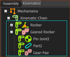
Kinematics-Tree of Gear-Pair
Add Gear-Pair removes one degrees-of-freedom.
|
Kinematics-Tree
|
Videos of Add Gear-Pair
Simple Gear-Pairs:

Video: Add a Gear-Pair (Simple)
Epicyclic Gear-Pairs:
Video: Add a Gear-Pair (Epicyclic)