What is a Plane?
A Plane is a flat surface, defined by its Local XYZ-axes. The XY axes are coplanar with the Plane. The Z-axis follows the usual Right-Hand-Rule. |
Use Visibility toolbar > Show Solids in Mechanisms to see Planes in Mechanism-Editors.
See also: Add Plane - Model-Editor
Add Plane (in a Mechanism-Editor)
In a Mechanism-editor, you can add a new Plane:
•that is parallel to a Plane you select. You can control the distance from the reference Plane - see FORMAT 1
•whose origin is at the start-Point of a Line* and the Plane of the Mechanism element to which the Line is descendant.
You can rotate the new Plane about the XYZ axes - see FORMAT 2
|
STEP 1:Start the Add Plane command
|
||
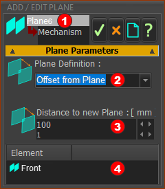 FORMAT 1: Add Plane to Plane |
The Add Plane dialog opens. In the Mechanism-Editor, the default format is:
|
||
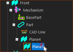 |
STEP 2:Click a Plane.
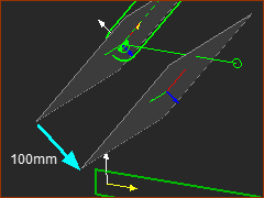
When you click a Plane, it shows in the Element box A preview of the new Plane is also in the graphics-area immediately. |
||
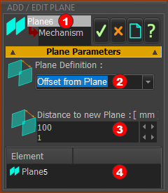 |
STEP 3:Edit the Parameter
Distance to new Plane - to Plane 6 |
||
 |
STEP 4.Complete the Add Plane command
Result
|
STEP 1:Start the Add Plane command
|
|||
 FORMAT 1: Add Plane to Plane |
The Add Plane dialog opens. In the Mechanism-Editor, the default format assumes you will select a Plane.
|
||
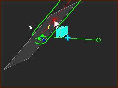 |
STEP 2:Click a Line*.
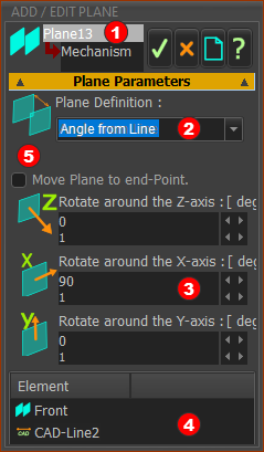
* Line, CAD-Line, or a Part's X-axis or Y-axis When you click a Line, the Line and the Plane (see below) to which the Line is descendant (great-grand-child - Plane > Mechanism > Part > Line ) show in the Element box There is a preview of the new Plane in the graphics-area, immediately. Note: Default is Rotate around X-axis = 90. |
||
 FORMAT 2: Add Plane to Line |
STEP 3.Edit the parameters
STEP 4.Complete the Add Plane command
|
||
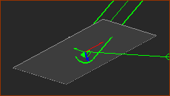 |
Result
|
||
Video:
Video: Add Plane to a Line, CAD-Line, or the X- or Y-axis of a Part
