2D-Cam > Display tab

2D-Cam dialog > Display tab
Display tab
There are two formats: Short and Extended. Short format
Extended format
The Pitch-Center is the path of the center-point of a Follower-Roller bearing relative to the Cam-Part. The Pitch-Center path is meaningful only when the Follower-Profile is a circular roller bearing. |


 |
|
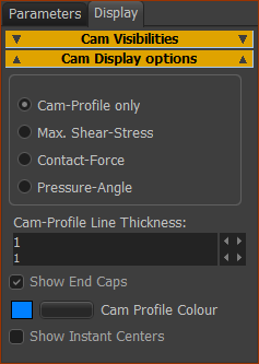
Display Cam-Profile as:
* Configure the Power Source to calculate correctly. |
|
Cam-Profile Line Thickness: (default =1) Edit the thickness of the Cam-Profile. Cam-Profile Color button Edit the color of the Cam-Profile in the graphics-area. Different colors are useful when there are many Cam-Profiles in your model. TOP-TIP - rename the 2D-Cam element to the color you select for the Cam-Profile. Show Instant centers : For the kinemagicians! |
|
 Without and With End-Caps |
|
Enable Show END-Caps check-box. This check-box shows only when MechDesigner detects that the Cam-Profile is “open”. A Cam-Profile is open if its start and end are not in the same place. With Slot-Cam types, it is frequently possible to close the Cam-Profile with End-Caps - see Note:
|
 |
◉ Cam Profile Outer Pitch-Center Path |
 |
◉ Maximum Shear-Stress
Notes: Maximum Shear-Stress is below the surface, at: • 0.78 × Contact-Width for Line contact • 0.48 × Contact-Width for Elliptical contact Maximum Shear-Stress is: • 0.3 × Contact Stress for Line and Elliptical contact |
 |
◉ Contact Force
|
 |
◉ Pressure Angle
See also Pressure Angle |