2D-Cam > Roller Life tab
Preparation
The Follower-Roller* bearing you select in this tab controls (overwrites) the Radius dimension of the Follower-Roller in your model. Before we can calculate the Roller Life, you must: •Add a radius dimension to the circle sketch that represents the Follower-Roller bearing in the Follower-Part •Make sure that a 2D-Cam or a Conjugate Cam FB is the power-source for the Follower-Part - see Configure Power Source * Other names used for “Follower-Roller ” are: Cam-Follower, Track-Roller, Track-Follower, ... . |
To Calculate the Roller Life, you must:
In the Parameters tab
In the Parameters tab > Enable Lifetime, Edit Safety Factor STEP 1:Enable Show Roller and Cam Life STEP 2:Enter a Safety Factor (CAM) Note: The Safety-Factor we apply to the Follower-Roller is equal to the square of the Safety-Factor (Cam). For example: If Safety Factor (Cam) = 1.1, then the Safety-Factor (Follower-Roller) = 1.21. Top-Tip
|
In the Roller Life tab
STEP 1: Select a Follower Roller bearing manufacturer. E.g. : SKF STEP 2: Select a Part-Number for a Follower-Roller bearing. E.g. : KR 16 EITHER to calculate the “Basic Rating Life”STEP 3a: CLEAR the Enable ISO 281 Modification Factors check-box STEP 4a: Analyze the Basic-Rating Life,
OR to calculate the “Modified Rating Life”STEP 3b: ENABLE the Enable ISO 281 Modification Factors check-box STEP 4b:Enter the ISO 281 Modification Factors
STEP 5b: Analyze the Modified-Rating Life ,
|
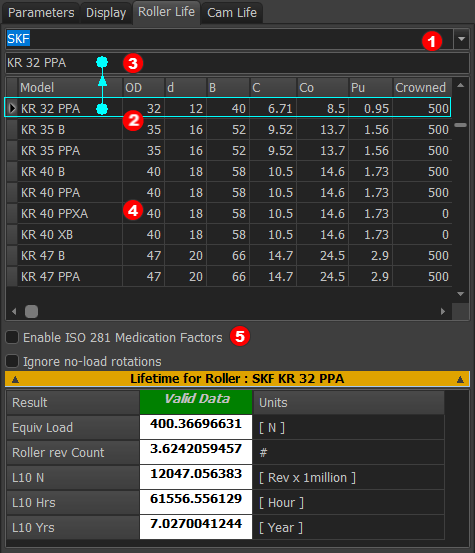
STEP 1:Select a Roller bearing manufacturer.
 Drop down list for |
1.Click the drop-down list arrow 2.Select a bearing manufacturer The available bearing manufacturers are: SKF, INA/FAG, KOYO, NSK, THK When you select a manufacturer, the bearing Part-Numbers and their parameters show in the table below. |
STEP 2: Select a Roller bearing from the table ![]()
Note:
1.Click a Part-Number in the table We copy the Part-Number you click to the box above We also move the Part-Number you select to the top of the table. |
|
|
|
When you select a Follower-Roller Part-Number, we may change your model.
|


EITHER
To calculate the Basic Rating Life
STEP 3a:ISO 281 check-box
CLEAR the Enable ISO 281 Modification Factors check-box |
STEP 4a:Analyze the Basic Rating Life,
In the Lifetime for Roller separator: Analyze the Basic Rating Life results for the Follower-Roller bearing. The results do not use the Reliability Modification Factor, , or the Systems-Approach Modification Factor, . See more - Lifetime for Roller Results |
or
To calculate the Modified Rating Life
STEP 3b:ISO 281 check-box
CHECK the Enable ISO 281 Modification Factors check-box |
STEP 4b: Enter the ISO 281 Modification Factors
 ISO 281 Modification Factors We calculate for you the and modification factors as you enter the parameters.
|
The bearing's modified life is one in which there is a 90% reliability that the bearing survives the “modified” number of rotations, if manufactured with commonly used high quality material, of good manufacturing quality, and operating under conventional conditions. The Reliability Modification Factor when the reliability is 90%. To apply a different percentage to the reliability of reaching the modified number of rotations: •Use the drop-down to select a percentage. The Reliability Factors in the drop-down list (90 to 99.95%) are those recommended in ISO 281. or •Enter a percentage. In this case, we find for you a Reliability Factor near to those that are recommended in ISO 281. |
 Operating Viscosity
The viscosity of the oil, or base-oil in a grease, at the operating temperature is function of the Viscosity Grade and Viscosity Index of the oil. We calculate for you the viscosity of the oil at the operating temperature Enter these five parameters: •Oil Operating Temperature . You may know the oil's operating temperature from experience or from tests. Then for the oil •Temperature - usually 40ºC •Viscosity at Temperature •Temperature - - usually 100ºC •Viscosity at Temperature Rules: and Notes: Lubricating Oil and Grease datasheets usually provide the Viscosity at and at . If you know the ISO Viscosity Grade of the oil, then yo: and |
 Lubrication Type
Select one of these lubrication methods: ◉Oil Filtered On-Line: Circulating oil lubrication with the oil filtered on-line before being supplied to the bearings ◉Oil Filtered Off-line: Oil bath lubrication, or circulating oil lubrication with off-line filters (or without filtration) ◉Grease ISO 281 does not consider Oil-Mist Lubrication. |
![]() Contamination Factors for each Lubrication-Type
Contamination Factors for each Lubrication-Type
Oil Filtered On-Line
Select the Filtration Ratio, , from the drop-down list box, The operating, or actual, Filtration-Ratio of the oil should be as good, and if not better, than the Filtration-Ratio you select. • - the particle size of the contamination, calibrated to ISO 11171 • - filtration ratio at contamination particle size The designation (c) signifies that the particle counters — of particles of size — shall be APC (automatic optical single-particle counter) calibrated to ISO 11171. Also, the oil system shall have cleanliness within the range indicated by the cleanliness code according to ISO 4406.
|
Oil Filtered Off-Line
Select the Cleanliness Codes from the drop-down list box that represents the anticipated operating conditions, according to ISO 4406.
|
Grease
Select the Level of Contamination from the drop-down list box that best represents the operating conditions.
|
STEP 5b:Analyze the Modified Rating Life,
In the Lifetime for Roller separator: Analyze the Lifetime results for the Follower-Roller bearing. The results apply the Reliability, , and the Systems-Approach, , Modification Factors. See more - Lifetime for Roller Results |
Roller Lifetime RESULTS
Basic Rating Life,
states that ...
... if the bearing load, , is equal to the Basic Dynamic Load Rating, , then there is a 90% reliability that the bearing survives 1 million rotations, if manufactured with commonly used high quality material, of good manufacturing quality, and operating under conventional conditions.
Roller Life : Bearing P/N

Basic Life for the seleced Roller bearing
Equivalent Load Because the Contact-Force and the Roller speed are continually changing, we must calculate an Equivalent Load.
Roller Rev Count The number of times the Follower-Roller rotates for each machine-cycle and cam rotation. Millions of Follower Rotations
Machine Operation in Hours We also calculate the Roller Life in “hours”. Basic Rating Life (Hours)
Machine Operation in Years We also calculate the Roller Life in “years”. One year is 8760 hours (24hours, 365 days). Basic Rating Life (Years)
|
Modified Rating Life,
We calculate for you the Modified Rating Life when you enable ISO 281 Modification Factors.
Roller Life : Bearing P/N

Modified Life for the selected Rollerbearing
Equivalent Load, Because the Contact-Force and the Roller speed are continually changing, we must calculate an Equivalent Load. Also, there are factors that continually change the value of . Thus we subsume into the calculation for Equivalent Load, .
Follower Roller Rev Count The number of times the Follower-Roller rotates for each machine-cycle and cam rotation. Millions of Follower Rotations , In catalogs, you will usually see this equation:
However, because the rotational speed, , the load, , and the modification-factor, , are not constant, we subsume them into an equivalent load, .
Machine Operation in Hours We also calculate the Roller life in hours. Modified Rating Life (Hours)
Machine Operation in Years We also calculate the Roller-Life in years. One year is 8760 hours (24 hours, 365 days). Modified Rating Life (Years)
|
WARNING: Roller Lifetime Results
Actual Operating Life It is not possible to calculate the actual operating life, as there are many different possible installation and operating conditions. One method to estimate the operating life is to compare the installation and operating conditions with similar applications.
|
Bearing Life Modification Factors
Life Modification Factors for Reliability,
The Reliability Factor is constant for all application conditions. The drop-down list has the standard Reliability Factor percentages (90 to 99.95%), as given in ISO 281. Modified Life Rating (at reliability) (millions of revolutions)
|
Life Modification Factor: a System Approach,
The Life Modification factor,, is a complex interaction between oil or grease viscosity-grade, filtration, contamination, oil operating temperature, fatigue load capacity of the roller, rotating speed, and the diameter of the roller. The equations given in ISO 281 to calculate these factors are empirical, complex, and interrelated. All of the factors, except , are a function of the rotating speed and bearing load. In a cam mechanism, the speed and load on the roller continually change. Therefore, we calculate for you the factors at each step and integrate them to find their equivalent values.
|
Fatigue Limit of Bearing, ()
ISO 281 defines the fatigue load, , for a bearing as the load below which metal fatigue does not occur. With poor lubrication, or contamination of the lubricant, the bearing can fatigue at loads which are significantly below the fatigue limit,. For the fatigue limit to be a valid value, the lubricant film must fully separate the rolling elements from the raceways and that dents from contaminants from handling do not exist on the rolling surfaces. The contamination factor, takes into account how the level of solid particle contamination of the lubricant influences the calculated bearing fatigue life. The particles cause indentations in the rolling surfaces of the bearing, and these indentations increase the local contact stress, which reduces the expected fatigue life. • means perfectly clean conditions without any indentations. • means severely contaminated conditions resulting in pronounced indentations. In the SKF rating life model, contamination, designated by the contamination factor, , acts as a stress raiser, thereby reducing the fatigue load limit to . We then compare the reduced fatigue load limit, , to the actual bearing load, , to give a fatigue resistance value of •Conditions that are clean and a load that is less than the fatigue load limit give a high fatigue resistance value. •Conditions that are contaminated and a load that is more than the fatigue load limit give a low fatigue resistance value. The stress-raising influence of contamination on fatigue depends on a number of parameters, including: bearing size, relative lubricant condition, size and distribution of solid contaminant particles, and types of contaminants (soft, hard, etc.). Therefore, it is not meaningful to enter a value for the contamination factor that has general validity. If a catalog does not list the Fatigue Load Limit, and the mean bearing diameter is less than . (nearly all Follower-Roller Bearings are less than ), then we use this approximation: |
|
|
Roller and needle bearings, with a Mean Diameter < 100mm. |
|
Ball bearings, with a Mean Diameter < 100mm |
Mean Diameter = (Outside Diameter + Inside Diameter) / 2 |
|
Viscosity Ratio,
The Viscosity Ratio, , indicates the quality of the lubricant film formation. The lubricant-film separates the raceway and rolling-elements. The Viscosity Ratio, , is expressed as:
Notes: A Viscosity-Ratio < 0.1 is outside of the limits of ISO 281. It is near to metal-to-metal contact. A Viscosity-Ratio - 4 is the maximum. ISO 281 states that Viscosity-Ratio = 4 if you calculate it to be greater than 4. A Viscosity-Ratio < 0.1 is the outside the scope of ISO 281. A Viscosity-Ratio > 4 is getting too high for bearings. The needles or balls may slide and refuse to roll in the 'thick-oil', or the shearing of the oil may churn and increase the oil and bearing temperatures. A Viscosity-Ratio in the range of is approximately ideal. Other Notes Note 1: Viscosity Ratio , assumes that surface finish is for good quality Follower-Roller bearings. Note 2: An approximate relationship between the Film Thickness Ratio , and Viscosity Ratio , is:
|
Reference Kinematic Viscosity,
The Reference Kinematic-Viscosity, (sometimes called the Rated, or Required Viscosity) is the viscosity that is required to separate the surfaces of the rolling elements and races in the Follower-Roller bearing.. It assumes that the oil is a mineral oil, with a Viscosity-Index of approximately 100. ISO 281 allows Synthetic oils. |
|
if |
|
if |
|
|
- inside diameter of Follower-Roller |
- outside diameter of Follower-Roller |
|
Kinematic Viscosity at operating temperature,
We calculate for you the Viscosity, , at the Operating Temperature, , from the Viscosity at two other temperatures. The lubricant's data-sheet usually specifies the Viscosity at ( ) and at ( ) You must enter all five parameters in the dialog: •2 x temperature: and •2 x viscosity: and at temperature and •Operating-Temperature: . We calculate the Viscosity, at the Operating-Temperature, . |
Contamination Factor,
If a contaminant particle moves to the inside of a bearing, the rollers (or balls), outer-race, and inner-race are prone to dent because of the small internal bearing clearances and the small rolling radii of the rollers (or balls). An indent leads to localized stress, which will decrease the life of the bearing. Severe contamination may even prevent the rollers (or balls) rotating. The contamination factors that reduce the lifetime of a Follower-Roller bearing are a function of the: •diameter of the Follower-Roller •lubricant film thickness (viscosity ratio, ) •size, type, and hardness of the particle contaminant. Guide values for the contamination factor are in the table below. They are typical levels of contamination for well lubricated bearings. Contamination and Lubrication Method. We can find for you the contamination factors with these lubrication methods:
|
|||||||||||||||||||||||||
Circulating oil lubrication with On-Line Filtration, before being supplied to the bearings.
|
|||||||||||||||||||||||||
Oil bath Lubrication, or Recirculating Oil Lubrication, with Off-Line Filtration.
NOTE
|
|||||||||||||||||||||||||
Grease Lubrication, Contamination Factors
|
|||||||||||||||||||||||||
Simplified Values for the Oil Contamination Factor ,
Contamination Level for Grease Lubrication
|
Contamination Levels for Oil, ISO 4406
The table below gives Scale Numbers as a function of Particle Contamination (particles/ml) - it is from ISO 4406 A three number code defines the amount of contamination for three particle sizes: 4, 6, and 14 μm. Each time a Scale Number increases by 1, the quantity of particles is doubled for a particular particle size. Example: ISO code = 21 / 19 / 17 This Contamination Class describes a fluid containing: •between 10,000 and 20 ,000 particles of ≥ 4 μm(c) per 1 ml sample •between 2,500 and 5 ,000 particles of ≥ 6 μm(c) per 1 ml sample •between 640 and 1 300 particles of ≥ 14 μm(c) per 1 ml sample If the leading number is missing, then that size of particle is not counted.
|