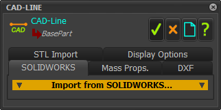
CAD-Line > SOLIDWORKS tab
See also: Mass-Properties tab, DXF tab, STL Import tab, Display Options tab.
Use the CAD-Line > SOLIDWORKS tab to import one SolidWorks Part/Assembly document ( SOLIDWORKS refers to their CAD files as "documents" ). onto a CAD-Line.
Before you import a document from SolidWorks:
•Make sure the SOLIDWORKS Part/Assembly document you want to import is open in SOLIDWORKS and it is the active document. •Make sure the SOLIDWORKS Part/Assembly document has a file-name. •Usually, add a Coordinate-System feature to the SOLIDWORKS Part/Assembly document to align it with the CAD-Line. •Usually, simplify the SOLIDWORKS document to reduce the complexity of the model. Warning: The SOLIDWORKS Part/Assembly document does not import into MechDesigner if, in SOLIDWORKS, you use a Chinese Traditional font to name a Configuration. Rename the Configuration with a Western font. |
Also, use the CAD-Line > SOLIDWORKS tab to:
•Control the surface accuracy of the CAD-Solid* •Remove a SOLIDWORKS Part/Assembly document from the CAD-Line. •Reopen the SOLIDWORKS Part/Assembly document in SOLIDWORKS that you have previously imported onto the CAD-Line. •Rename the CAD-Line to the name of the active SOLIDWORKS Part/Assembly document. * Cad-Solid is the name we use for a CAD model that you import onto a CAD-Line with the CAD-Line dialog. |
CAD-Line dialog
SOLIDWORKS tab

CAD-Line dialog> SOLIDWORKS tab
 CAD-Line dialog > SOLIDWORKS tab |
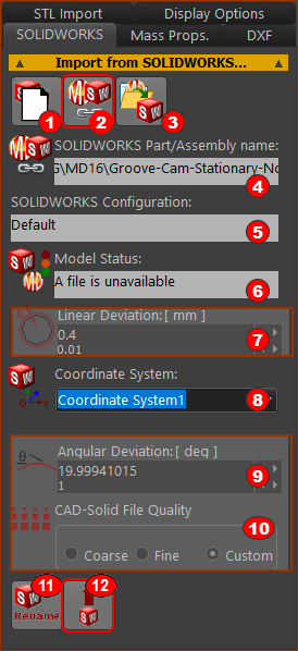
STEP 1: Click the Read WAIT until a: •SolidWorks® Part/Assembly name (read-only) shows in box •SolidWorks Configuration (read-only) shows in box •SolidWorks Coordinate System shows in box •Model Status (read-only) shows in box
STEP 2: If there is more than one Coordinate-System, select a Coordinate-System STEP 3: Click the Import Wait - a large model can time to import. When the model is in MechDesigner, we Toggle in Solids in Mechanism-Editors.
|
||
Optional Buttons(
CAD-Solid File Quality
|
|||