CAD-Line > STL Import tab
Use the STL Import tab to:
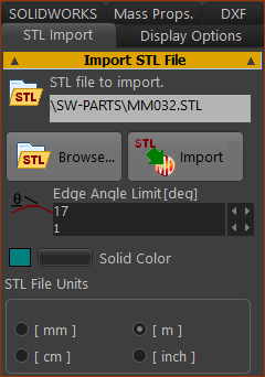
•Import / re-import one CAD-model with the STL file-type •Change the STL File Linear Units , usually to be equal to the linear units of the original STL file •Edit the Edge Angle Limit to remove “ghost” lines on the CAD-Solid which you can see on the faces of the CAD-Solid in MechDesigner. See more : STL Files |
If you do not have SolidWorks, in your CAD software:
•Rotate your CAD model to align its XYZ axes with the XYZ axes of the CAD-Line. In the CAD software > Save as... dialog: •Select the STL file-type •Select Binary •Select the Linear units If you cannot select the Linear units they will be SI units - meters (m). |
After you import an STL file:
See CAD-Line > Display Options tab to move the STL file in the X, Y, and Z-axis directions. See CAD-Line > SOLIDWORKS tab to remove the CAD-Solid from the CAD-Line. |
CAD-Line dialog
STL Import tab

CAD-Line dialog > STL Import tab
|
To import (or re-import) an STL file:
Options:
Top-Tip
|
|||
 Image with too many Facet-Edges |
||||
 Image with Facet-Edges OK |
About STL files
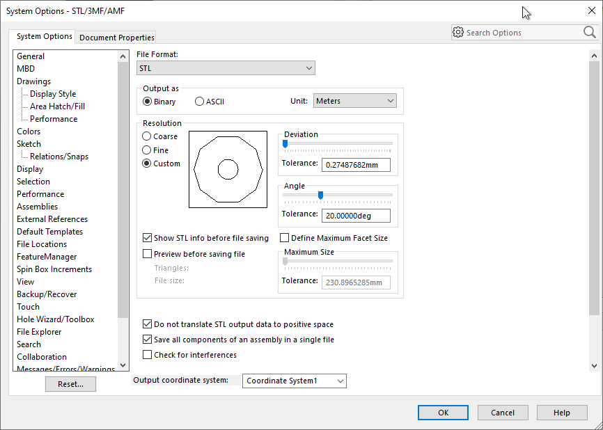
The STL file tessellates to approximate the surfaces of the original CAD model as a mesh of triangles. Each triangle is a small face, also called a facet. The number of facets is a function of: •the complexity of the original CAD model, and •how accurately you want the STL file to tessellate the original CAD model. The accuracy of the STL File is a function of the Linear Deviation and the Angular Deviation parameters in the SolidWorks tab. The size of the STL file increases the more accurately the STL model represent the original CAD model. |
STL file and file-size
If you want to import many STL files, you also want a: Small file-size for each STL file, ... AND each STL file to appear to be equal to the original CAD model, ... AND to see only those facets that are real edges in the CAD model. |
Strategies to reduce the STL file-size.
Strategy 1: Reduce the complexity of the original CAD Model to reduce the STL file-size Add a new configuration for the CAD model. In the new configuration: •Do a geometry check to find if it has any small gaps or whiskers •Suspend external fillets and internal fillets, especially if they do not have a function •Delete fillets, or replace with chamfers when fillets are not functional •Suspend all fasteners •Suspend fastener holes and hole features •Suspend all cosmetic details •Replace complex models you may have downloaded from the internet with simplified models, e.g. bearings. Strategy 2: Reduce the accuracy of the STL file There parameters are in the CAD-Line > SOLIDWORKS tab. Linear Deviation : The maximum Linear deviation (distance) between the surface of the original CAD model and the tessellated surface of the STL file. Angular Deviation : The maximum angular deviation between adjacent facets of the tessellated surface of the STL file. If you do not have SolidWorks, find these parameters in your 3D-CAD before you save your model as the STL file. It is possible Linear and angular deviation are options in the Save as > STL file-type dialog. Strategy 3: Use the Edge Angle Limit parameter - see Import STL File above STL files will show their facets if the angle in Edge Angle Limit is less than the facet of the CAD-Solid. Experiment. Import the model again each time you edit Edge Angle Limit (try 80 degrees). Examples Below, the two images are of the same SOLIDWORKS part. They appear to be identical. However, there is a 10x difference in the number of facets and vertices, and consequently the STL file size. MechDesigner will continue to be responsive. |
|
 STL: Large number of Vertices |
BAD - many facets •Linear Deviation = 0.014mm •Angular Deviation = 0.4º There are •119132 vertices •~40000 triangles •The STL file size is 3.5 Mega Bytes |
 STL: Few number of Vertices |
GOOD - few facets •Linear Deviation = 0.5mm and •Angular Deviation = 5º There are: •7533 vertices •~2500 triangles •The STL file size is 0.365 Mega Bytes |
 |