CAD-Line
Each Part has a CAD-Line between its start-Point and its end-Point.
When you add a Mechanism-Editor, the Base-Part does not automatically have a CAD-Line. However, you can edit the Base-Part to add CAD-Lines to the Base-Part.
You can also edit any Part in the model to add CAD-Lines.
See Add CAD-Line
Use the CAD-Line dialog to:
•Import a CAD-Solid* from SolidWorks, OR import an STL file from other CAD. •Import Mass-Properties from SolidWorks, AND/OR enter User Mass-Properties. •Display a DXF-Drawing** and edit its color. •Change how to display a CAD-Solid* - Color, Transparency, Edge, ... . * Cad-Solid is the name we use for a CAD model that you import onto a CAD-Line with the CAD-Line dialog. ** You must first import the DXF-Drawing with File menu > Open DXF. |
How to open the CAD-Line dialog
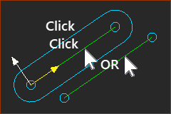
 Double-Click a CAD-Line to open the |
To open the CAD-Line dialog
|
|
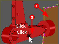
 Double-Click a CAD-Solid to open the CAD-Line dialog |
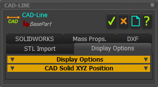
The CAD-Line dialog is now open.
 CAD-Line dialog |
CAD-Line dialog tabs:Mass PropertiesDXFSTL ImportDisplay Options |