Efficiency.
|
Prepare this simple model. Add a:
The kinematic-chain is kinematically-defined. The Part is a Rocker. It is a Motion-Part. STEP 1: Start the Part-Editor to edit the Part.
|
||
|
|||
|
STEP 2: Use the Part-Editor to add a 3 Lines and 3 Arcs
|
||
|
STEP 3: Click Geometry toolbar > Merge-Points tool
|
||
|
STEP 4: Close the Part-Editor when the Sketch-Loop is complete.
|
|
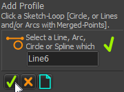
STEP 1: Start the Add Profile command
|
||
|
STEP 2: Is the sketch-element is in the Command-Manager?
|
||
|
STEP 3: Complete the Command
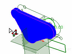
The default color of the Profile is Pink, which you see from the Front-View. You will not see the sketch-elements from the Front View. |
||
|
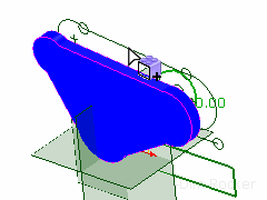
STEP 4: View the MD-Solid in the Model name-tab.
|
||
|
STEP 5: Click the Mechanism name-tab.
|
|
STEP 1: Add the Extrusion element in the Selection-Window
|
|
 Selection-Window |
STEP 2: Edit the Extrusion (from the Selection-Window)
|
|
 Assembly-Tree |
STEP 3: Edit the Extrusion (from the Assembly-Tree)
|
 Extrusion Parameters  Color, Opacity, Quality  Mass Properties |
|
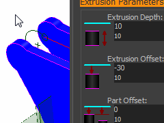
Extrusion Parameters Three parameters control the position of the Profile relative to the Mechanism-Plane: Extrusion Depth specifies the distance to the Secondary-Contour from the Primary-Contour. This is always a positive value. Extrusion Offset moves the Primary Contour along the Z-Axis of the Part. Part Offset moves the Primary Contours of ALL the Extrusions in a Part. The other parameters edit the Properties of the Extrusion. Show or Hide Extrusion, Extrusion color, Change Transparency, Graphic Quality, Material Density MechDesigner calculates the Mass and Inertia from the Density, Profile Contour, and the Extrusion Depth parameters. |
|
|
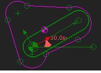
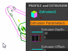
Extrusion Depth: •When you edit the Extrusion Depth, the Secondary Contour moves along the Z-axis. In the image to the left: •Extrusion Depth is 10mm. •The Primary Contour is coincident with the sketch-loop. The sketch-loop may show in the graphics-area over the Profile. |
|
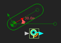
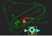
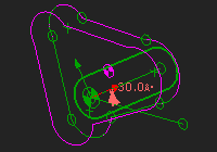
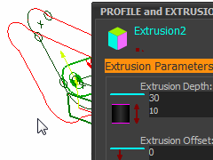
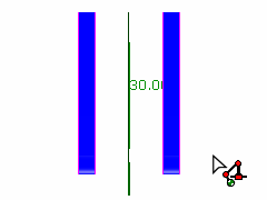
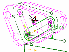
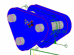
STEP 1: Edit the Extrusion Depth. •I have edited the Extrusion Depth to 30mm with the spin-box tool. The Spin-Increment is 10, so it took two clicks! •The Secondary Contour moves away from the Primary Contour. The Primary Contour does not move when you edit the Extrusion Depth. Note: If the model is large, the Extrusion Depth parameter can take a few seconds to update. |
|
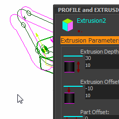
Extrusion Offset and Part Offset •There is one Extrusion in this Part. Therefore, comparison between Extrusion Offset and Part Offset is not immediately clear. •We adds the Extrusion Offset and Part Offset. They calculate where the Primary contour is relative to the Mechanism-Plane. These values are Positive or Negative. •The Secondary contour always moves with the Primary contour. STEP 2: Edit the Extrusion Offset. •The Extrusion Offset is -10mm. •The Primary contour moves off the Mechanism-Plane in a negative direction by 10mm. •The new positions of the Primary and Secondary contours are in the image to the left. |
|
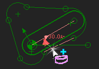
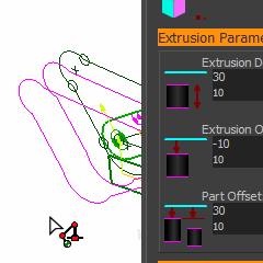
Part Offset: •A Part may have more than one Extrusion and it may be convenient to move all of the Extrusions together. •The Part Offset applies to all Extrusions in a Part •Add the Part Offset to the Extrusion Offset to equal the total offset of the Primary contour from the Mechanism-Plane. STEP 3: Edit the Part Offset •The Part Offset is 30mm •Add the Part Offset to the Extrusion Offset. The total offset is (-10+30) = 20mm from the Mechanism-Plane. |
|
STEP 1: Toggle IN Visibility toolbar >'Show Model Element in Mechanism' |
|
STEP 2: First, edit the Extrusion again. Remember, to Edit an Extrusion: 1.Click the Profile in the graphics-area 2.Right-click the Extrusion in the Selection-Window 3.Click Edit element in the shortcut-menu Enter these values in the Extrusion dialog: •Extrusion Depth = 10 •Extrusion Offset = 20 •Part Offset = 0 |
|
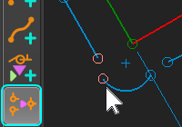
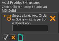
STEP 3: Add a new Profile
1. In the Mechanism-Editor, Use the 2.In the graphics-area, select a Line or Arc from the same sketch-loop. 3.Click OK in the Command-Manager. |
|
STEP 4: Edit the new Extrusion. 1.Click the Profile contour. 2.Right-Click the Extrusion in the Selection-Window 3.Click 'Edit' Enter these values: •Extrusion Depth = 10 •Extrusion Offset = -30 •Part Offset = 0 |
|
STEP 5: Look at the two extrusions with the 'Right View' •In the Mechanism-Editor, use the View > From Right menu option. •Note: To make the Extrusions symmetrical to the Mechanism-Plane: the Extrusion Offset of the Extrusion 'behind' the Mechanism-Plane must compensate by the Extrusion Depth (Part Offsets is zero). Experiment! •The Extrusion Depths are 10. •The Extrusion Offsets are 20 and -30 |
|
STEP 1: Edit the Part in the Part-Editor Double-click the Part-Outline, or a sketch-element, in the Part. |
|
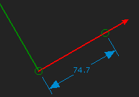
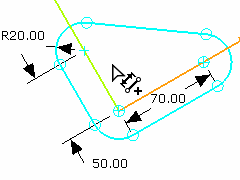
STEP 2: Add dimensions and constraints to the sketch so the sketch-elements change color to indicate they are Fully-Defined. I have added: •Tangent constraints between the Arcs and Lines •Coincident constraints between the center of the bottom two Arcs and the ends of the CAD-Line •Coincident constraint between top Arc and the vertical Y-axis •Equal constraints to the Arcs •Dimensioned the Arc and the distance to the center of the top Arc •Re-dimensioned the length of the CAD-Line |
|
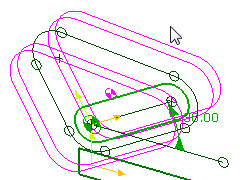
STEP 3: Review the Profiles Click the Visibility toolbar > Show Solids in Mechanism tool to hide the Extrusions You can see that the Profile contours and the Extrusions have also updated to the new shape of the sketch-loop. (For some reason, the Profile contours are 'White' in this image - they are usually Pink).
|
|
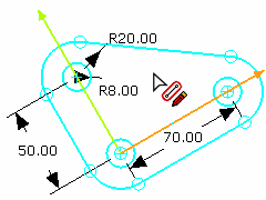
STEP 4: Add New Sketch-Elements Here, I have added three Circles to the sketch. The Circles are: •equal in size •coincident with center-Point of the Arc. A Circle is the most basic shape of a sketch-loop. |
|
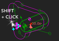
STEP 5: Add three new Profiles with the three Circles Do the commands three more times. AS BEFORE: Select Add Profile, select the Sketch-loop (the Circle), and click OK in the Command-Manager. ALTERNATIVELY, try this new technique! 1.Hover above the sketch-loop so it is selected – DO NOT click it 2.Right-Click 3.Click Add Profile from the contextual sensitive icon palette 4.Right-click to complete the command. (This is a keyboard shortcut for OK in the Command-Manager). |
|
STEP 6: Edit the Three Extrusions Here, we want the three Circles to be 'posts' between the two plates. Edit each Extrusion, and enter these values in the Extrusion dialog •Extrusion Depth = 80 •Extrusion Offset = -40 •Part Offset = 0 •Extrusion color – here all a light grey. |
|
STEP 1: Edit the Part 1.Double-click the Part-Outline, or a sketch-element in the Part. |
|
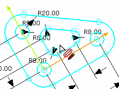
STEP 2: Add a Sketch-Loop that is the shape of the Hole: •See the new Sketch to the left •The sketch-loop that is the shape of the hole is 'inside' the sketch-loop used for the Profile. •Close the Part-Editor. |
|
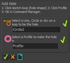
STEP 3: Add a Hole to each side 'plate' Use the In the Command-Manager: 1.Click a sketch-element on the sketch-loop intended to be the shape of the hole (an 'Arc' has the label 'Circle'). 2.Click the Profile with the Extrusion through which you want to cut the hole. 3.Click Do Steps 1-3 again for the other Extrusion |
|
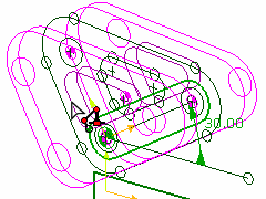
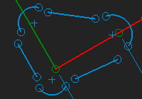
STEP 4: View Holes through Extrusions I have used the Display Filter to 'hide' Points. 1.With the Visibility toolbar > Show Solids in Mechanism Toggled OFF, it is possible to see: Sketch-loops (green) for the: •Primary Shape, the three Posts, and the Hole Profiles (white - but default color is Pink) •2 for the main shape, three for the posts, and the Hole Element (also white, usually Maroon |
|
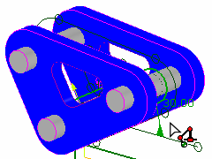
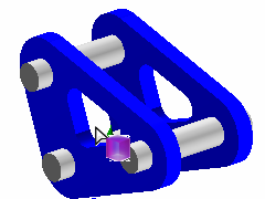
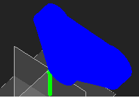
STEP 5: Solids the Extrusion in the Mechanism-Editor With the Visibility toolbar >Show Solids in Mechanisms Toggle ON it is possible to see: Extrusions: •2 Blue 'Plates' made from the one primary sketch-loop •3 Grey Posts/Pegs made from Circle sketch-loops •2 Holes derived from one sketch-loop |
|
STEP 6: Click the Model name-tab to review the model in the Model-Editor There are six lights to improve the display of the model. STEP 7: Right-click the Model element that is at the top of the Model Assembly-Tree. The Model dialog opens. Click the Lighting tab Also, see: Visibility toolbar > Solid Display Mode:
|