Summary of this Step
Add a Transforming-Mechanism to the Tool-Part. The Transforming-Mechanism is an R-R-R dyad. Join the Transforming-Mechanism to the Tool-Part and the Base-Part. Edit the Base-Part to add Geometry. MechDesigner calculates for you the motion-values of the two Parts in the Transforming-Mechanism. This is an introduction to Inverse-Kinematics. |
Terminology:
Terms : |
Definitions |
Transforming-Mechanism : |
A derived-name for the dyad in a kinematic-chain that transforms the motion of a Tool to the motion of the Follower. The Follower is usually located at a more convenient place in the machine. |
Inverse-Kinematics : |
We calculate for you the motion of the Parts in the Transforming-Mechanism from the motion of the Tool-Part whose motion you design in MotionDesigner. |
Dyad : |
A kinematic-term for two Parts and three joints that combine as a Transforming-Mechanism. |
Video of this Step

Video: Add the RRR Dyad ('Transforming' Mechanism)
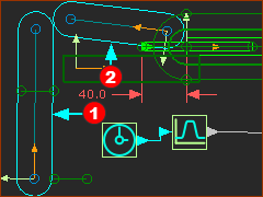
Why edit the Base-Part? To add sketch-elements so that we can join the Transforming-Mechanism to the Base-Part. Also, you need to join a Cam-Shaft to the Base-Part. STEP 1: Edit the Base-Part
|
||
|
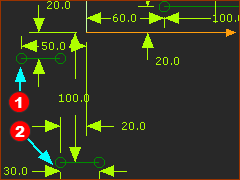
STEP 2: Add two Lines to the Base-Part.
|
|
|
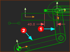
STEP 1: Add two Parts
The two Parts |
|||
|
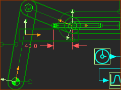
STEP 2: Add three Pin-Joints
When you complete STEP 2 Add three Pin-Joint, the Parts in the transforming-mechanism is kinematically-defined. |
|||
|
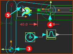
Closure...: We explain Closures in detail in Tutorial 2 Step 2.4 It is possible that the dyad assembles in a closure that you do not want. The R-R-R dyad has two closures. Do Step 3 if the Parts do not assemble in the closure you want. STEP 3: Change Dyad Closure
The two Parts in the dyad move to a different closure. STEP 4: Cycle the Model with the Transforming-Mechanism
You will see that the Transforming-Mechanism (dyad) moves with the Slider. Save you Mechanism |
|||
|
||||
If, as you cycle the model, the joints move apart, you can do one or all of these changes to your design:
Save you Mechanism |
||||