Add a Gear-Pair
We will add a Gear-Pair with an orbiting gear.
(See Tutorial 14 for more information on Gear-Pairs)
|
The Internal Gear will be fixed to the Base-Part. The External Gear will orbit inside of the Internal Gear. The External Gear has 1/3 the number-of-teeth of the Internal Gear STEP 1: Add a Rotating-Part - see Tutorial 1 for a complete list of instruction. 1.Add a Line to the Base-Part. 2.Add a Part to the Mechanism-Editor 3.Add a Pin-Joint between the Part and the Point at the left of the Line added to the Base-Part 4.Add a Motion-Dimension FB to identify the Part as a Rocker/Crank 5.Add a Linear-Motion FB 6.Connect the Linear-Motion FB to the Motion-Dimension FB |
|
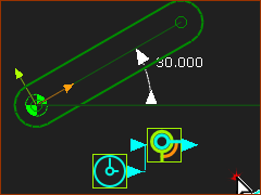
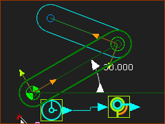
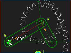
STEP 2: Add Part to the end of the Crank/Rocker 1.Add a Part 2.Add Pin-Joint between the end-Point of the Rocker and the start-Point of the new Part We are now ready to add a Gear-Pair
|
|
STEP 3: Add a Gear-Pair |
|
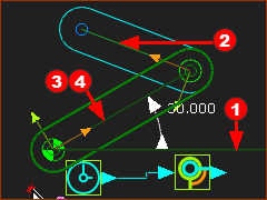
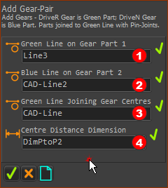
1.Click Machine element toolbar > Add Gear-Pair The four elements to add this Gear-Pair are:
Note: The Part-Editor will open automatically for you to select the length dimension |
|
To close the Command-Manager you can: 1.Right-click in the graphics-area (a shortcut) - or - 2.Click The default Gear-Pair has an: •External mesh •Equal Number of Teeth (z1 & z2) •A typical module (m) Use Edit menu> Application-Settings > Graphic tab > Display colors > Gear-Pair to change the color of the Gears to give a good contrast with Background color. Note: for information only. Pitch Diameter (D) = m*z1 and m*z2 (5*20=100mm) | and Circular Pitch (Pc) = m. π = D.π ∕ N |
|
STEP 4: Edit the Gear-Pair 1.Double-Click the Gear-Pair in the graphics-area (or see How to open a dialog) The Gear-Pair dialog opens. Edit the Gear-Pair as follows: •Define tab : Gear Mesh and Teeth > Gear 1: 60 Teeth | Gear 2: 20 Teeth | Internal Mesh (radio-button) •Parameters tab > Gear Tooth Parameters > Module = 5 2.Click 3.Cycle the model (ALT+C) to see that the Large Gear is stationary, and the Small Gear rolls around the inside of the Large Gear. |
|
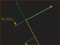
STEP 5: Edit the Part with 20 teeth to add a new Line We want the length of the new Line to equal the radius of the small Gear. The Pitch Diameter (D) = m × z1 and 5 × 20 =100mm 1.Part-Editor: Add Line : Drag to add a Line 2.Part-Editor: Geometric Constraint > Coincident Constraint | Click the start-Point of the Line and the start-Point of the CAD-Line 3.Part-Editor: Drag the end-Point on the Line to be in the –X direction 4.Part-Editor: Geometric Constraint> Add Equal | Click the new Line and the original CAD-Line 5.Part-Editor: Add Horizontal : click the new Line 6.Exit the Part-Editor |
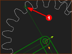
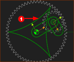
STEP 6: Add a Trace-Point to the end-Point of the new Line. 1.Mechanism-Editor: Click Kinematic-elements toolbar : Add Trace-Point 2.Mechanism-Editor: Click the end-Point 3.Mechanism-Editor: Click The Trace-Point is the path the Point makes in one machine-cycle |
|
|
If you cycle the machine (ALT+C as the Shortcut) you will see the Point at the end of the Line move along the Trace-Point. |
