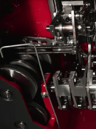
Cam-Terminology:
Terms : |
Definitions |
|---|---|
Cam (or Cam-Part) : |
The Part that supports the Cam-Profile shape. Its motion is the input to the Cam system. |
Cam-Shaft : |
The most common Cam-Part. It is rotating-Part (a shaft), to which you add the 2D-Cam (or 3D-Cam) as a Cam-Profile. A Cam-Shaft usually rotates with a constant angular-velocity. |
Cam-Profile : |
The curved surface of a 2D-Cam (or 3D-Cam) that imparts a motion to a Follower by point or line contact with the surface of a Follower-Profile. |
Cam-Track : |
A groove that is cut into a Cam-Blank with an Outer and an Inner Cam-Profile. |
Follower (or Follower-Part) : |
The Part that supports the Follower-Profile. Its motion is the output from the cam system. |
Follower-Profile : |
The surface of a machine component that is rigidly connected to the Follower-Part. The surface that is in continuous contact with the Cam-Profile. |
Follower-Roller : |
A common Follower-Profile that is cylindrical or barrel-shaped, and rigidly connected to the Follower-Part. |
Flat-faced Follower : |
A Follower-Profile that is a flat surface that is rigidly connected to the Follower-Part. |
Translating Follower : |
A Follower-Part that moves along a straight axis. |
Reciprocating : |
A sliding-Part that has a motion that is non-progressive. |
Rotating Follower : |
A Follower-Part that rotates about a fixed axis with a progressive or non-progressive motion. |
Oscillating : |
A rotating-Part that has a motion that is non-progressive. |
Progressive Motion : |
A motion that moves the Follower-Part generally in one direction. |
Non-Progressive Motion : |
A motion that returns the Follower-Part to its original position after each machine cycle. |
Indexing : |
A progressive, usually rotating motion. |
Indexer : |
A device whose input is a constant-speed Cam-Shaft and output is a rotating shaft with a progressive motion. After the cam-shaft rotates fully a number of times, the output shaft rotates by 360º. |
Cam-Blank : |
The material that you need before you cut the shape of the Cam-Profile. |
Introduction to the Cam Mechanical System.
|
The Cam Mechanical System has a: Simple Input-Motion Usually, the Cam-Part has a simple motion. It is said to be the input-motion. Complex Output-Motion Usually, the Follower-Part has a more complex motion. It is said to be the output-motion. Input-Transmission The mechanical components from the motor (power source) to the Cam-Part are said to be the input-transmission. Output-Transmission The mechanical components from the Follower-Part to the payload are said to be the output-transmission. Follower-Profile The element, connected to the Follower, that is in direct and continuous contact with the Cam-Profile. It is usually a Follower-Roller, and occasionally a Flat-faced Follower. Other more general shapes are possible. Payload : Other names for Payload are Load, Tooling, and End-Effector. |
|||||||||||||||||||||||||||||||||||
The design and selection of the mechanical components for the input-transmission and the output-transmission significantly affect the overall performance of the cam-system. The mechanical components are usually conventional machine-elements, such as shafts, gears, couplings, sliders, and linkages. They are usually connected together in series. You cannot design a cam in isolation of the other components in the mechanical system. The characteristics of the mechanical components that most significantly affect the performance of the Cam-System are the mass moment of inertia (or mass for linear systems), rigidity (or stiffness for linear systems), and backlash in the input-transmission and output-transmission. The motion you design for the payload is equally important. A poor motion will needlessly incite vibrations in any mechanical system. A good motion will give you a machine that lasts longer, jams less frequently, and has the same capital cost as a machine with poor motion-design. Motion-Design for a single axis is fairly straightforward. Motion-Design for multi-axis machines, with many interacting mechanisms and complex material-to-machine interactions, requires experience, skill and a good understanding of the motion-design requirements as a whole. Cam Mechanism : from the 'Power-Source' to the 'Payload'
|
||||||||||||||||||||||||||||||||||||
