Barrel Cams: 3 Planes and 3 Mechanism-Editors
 Image of Barrel Cam after it has been transferrred to SOLIDWORKS. |
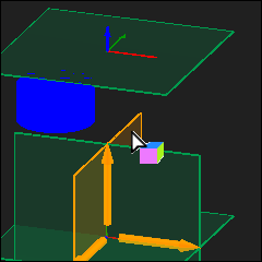
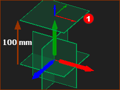
There are three Planes:
* When your model is to design a 3D-Cam only, use these three Planes. If the model has other machine elements, then use the Planes as required by the model. |
|
 Cam-Rib has two Follower-Rollers |
Rib Cams. This tutorial designs a Barrel-Cam that has a Cam-Groove. However, it is also possible to model a Barrel Cam that has a Cam-Rib - see image to the left. The Cam-Rib also has two Cam-Flanks. In the case of a Cam-Rib, you must add two Follower-Rollers. Contact us, if you need help to model the Barrel-Cam with a Cam-Rib. Note : the Track is also called a Groove. |
|
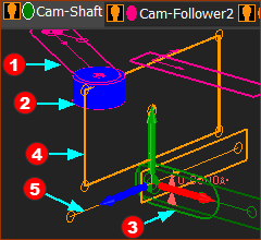
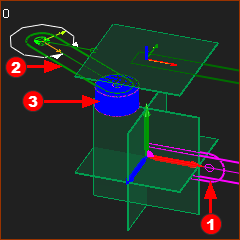
The Five Elements for a 3D-Cam:
") 5 elements for a Barrel-Cam (typical) |
There are five elements. With Barrel/Cylindrical Cams, the five(5) elements are on three(3) different Planes and Mechanism-Editors.
To see all of the elements from one Mechanism-Editor, do :
|
||||||||||||||||||
|
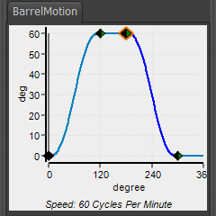
We must also design the motion for the Follower-Part in MotionDesigner.
|
 1: Add the Cam-Shaft
|
STEP 1: Add a new Mechanism-Editor for the Cam-Shaft ( see example: Tutorial 1 - a rotating-Part )
You immediately jump to the new Mechanism-Editor. STEP 2: Add a Line to the Base-Part
|
||
 The Cam-Shaft |
STEP 3: Add a Cam-Shaft - a Rotating-Part:
|
2: Add the Follower
|
STEP 1: Add the Plane and Mechanism-Editor for the Follower In the Model-Editor:
You jump immediately to the new Mechanism-Editor. |
||
|
Rename the Plane and Mechanism-Editors
We need to see the 'other kinematic and sketch-elements':
|
||
Above, the image shows the positions of the: •Cam-Shaft •Base-Part However, it is easier to add the elements to the Front View - Click F3 for the Front-View. |
|||
|
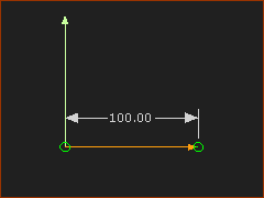
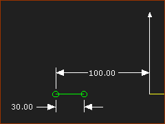
STEP 2: Add a Line to the Base-Part
|
||
 After STEP 4 |
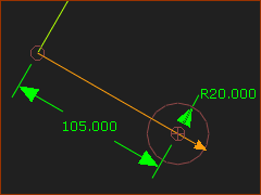
STEP 3: Add the Follower Part (Oscillating)
STEP 4: Control the motion of the Follower Part (Oscillating)
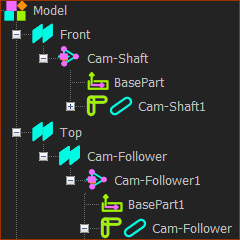
<<< The new names and hierarchy of the important-elements in the Assembly-Tree (actually the |
||
|
|||
3: Add the Follower-Roller
|
STEP 1: Add the Follower-Roller to the Follower
|
|
|
STEP 2: Add and Edit the Follower-Profile
|
|
|
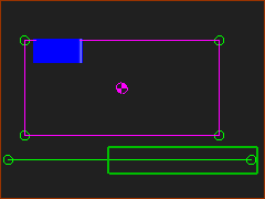
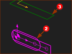
The Model after STEP 2
The elements in the image are:
|
3: The Cam-Blank and Rotational Axis
|
Rotational Sketch of the Cam-Blank: a sketch-loop of the rotational cross-section of the Cam, into which we can machine the Cam-Track. Rotational-Axis: the line that we revolve the sketch-loop of the Cam-Blank The sketch-loop is in a new Mechanism-Editor. STEP 1: Add a new Mechanism-Editor for the Cam-Blank
|
||
|
STEP 2: Add a sketch-loop and rotational axis for the Cam-Blank
|
||
|
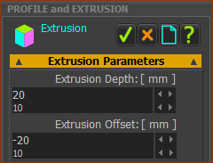
STEP 3: Add a Profile to the Cam-Blank
|
||
|
There are five elements. With Barrel/Cylindrical Cams, the five(5) elements are on three(3) different Planes and Mechanism-Editors.
To see all of the elements from one Mechanism-Editor, do :
|