Measurement FB
Use a Measurement FB to measure between sketch-elements in the same or different Parts. You can measure the: •Length of a Line, CAD-Line •Radius of a Circle, arc •Distance between two Points** § •Distance between a Line* and a Point** •Distance between two parallel Lines* •Angle between two Points** § •Angle between two Lines* •Angle between three Points** The output from the Measurement FB includes the dimension and its first and second motion derivatives. § - There are two(2) output-connectors when you measure between two Points* - see more details below * - Line, CAD-Line, X-axis, Y-axis. ** - Point, start-Point, end-Point, center-Point, and/or Motion-Point. |
Add Measurement FB
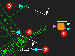 Measurement FB between two Points |
The Measurement FB In this example, the Measurement FB |
||||
Note:
|
|||||
Measurement FB
* Line, CAD-Line, X-axis, Y-axis ** Point, start-Point, end-Point, center-Point, Motion-Point. |
||
Image |
Sketch-Elements |
Measurement Dimension |
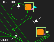 Length or Radius |
1.Click a Line or CAD-Line |
Length of the Line* |
1.Click a Circle or Arc |
Radius of the circle or arc. |
|
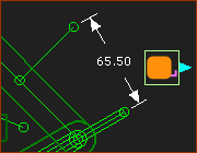 Distance - Point & Line |
1.Click a Point** 2.Click a Line* |
Perpendicular Distance between the Line and Point. |
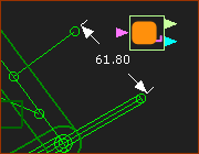 Distance - 2 Points |
1.Click a Point** 2.Click a Point** |
Linear Distance and Angle of two Points. |
A Measurement FB between two Points** has two output-connectors: - Top output-connector: distance between two Points, and first and second motion-derivatives - Bottom output-connector: angle between two Points, and first and second motion-derivatives |
||
Angle between three(3) Points** - Internal Angle and External Angle. ** Point, start-Point, end-Point, center-Point |
||
Image |
Sketch-Elements |
Measurement Dimension |
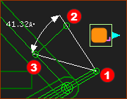 Internal Angle - 3 Points |
Three Points 1.Click 'Apex' Point** 2.Click Point** 3.Click Point** |
Internal Angle The angle is from |
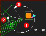 External Angle - 3 Points |
Three Points 1.Click 'Apex' Point** 2.Click Point** 3.Click Point** |
External Angle The angle is from |
Image |
Sketch-Elements |
Measurement |
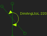 Angle - 2 Lines |
Two Lines 1.Click a Line* 2.Click Line** |
Angle - from eight(8) possible Angles. |
To display one of eight angles: Before you click in the graphics-area to place the Measurement Dimension and FB ... ... move your mouse-pointer around the apex of the two lines: CASE 1: Counter-clockwise : 4 angles < 180° : the Acute, Obtuse, Supplementary and Vertical angles CASE 2: Clockwise : 4 angles > 180° : the reflex angles - or the angles that are external to those angles of CASE 1. |
||
Video: Eight Measurement Angles between two Lines: Add Angle Dimensions between two Lines
|
||
How to use the Measurement FB:
You can connect a wire from the output-connector of a Measurement FB:
Note 1: To plot the Position, Velocity and Acceleration of the Dimension in the same graph. 1.Drag a wire from the same output-connector of the Measurement FB three times to different input-connectors of a Graph FB, 2.Use the Y–axis display options in the Graph Interface to display the three different motion-derivatives. Note 2: Check the messages in the Feedback-Area. “1 Mechanism dependencies detected”. This means, that the motion of a kinematic-chain is a function of (dependent on) the motion (measurement) of a different kinematic-chain. It is usually called Motion-Dependency. |