Feedback-Area
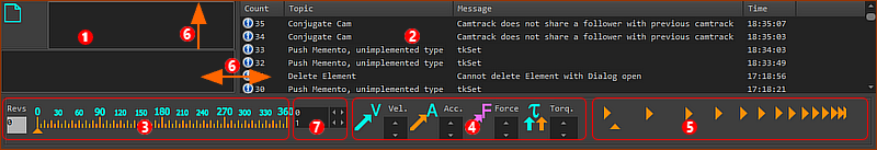
The Feedback-Area is below the graphics-area.
It has five areas.
 Extended Hints OR Element Properties
Area  shows an Extended Hint for a command or an Element Property for an element. shows an Extended Hint for a command or an Element Property for an element.
Element-Properties:
When you move your mouse above an element in the graphics-area, area shows the element's kinematic-properties and/or kinetostatic-properties.
Extended Hints:
When you move your mouse above a command in a toolbar, area shows a tool-tip.
Notes:
To see all of the Extended Hint and/or Element-Property, you may need to drag the separator-bars  upwards and/or to the right by a short distance. upwards and/or to the right by a short distance.
You can choose to deselect “Show Element-Properties Dynamically” from Application-Settings > Accessibility tab. Then, only the Extended Hints show in area .
|
|
 Messages
Message information:
Count :
|
The message number (top message is most recent)
|
Topic :
|
Importance Level:  – Information; – Information;  – Warning; – Warning;  – Error - save your work now! – Error - save your work now!
|
Message :
|
The message that you should read!
|
Time :
|
When the message was displayed.
|
To clear the messages:
1.Right-Click, with your mouse-pointer in the Messages area
2.Click Clear Messages in the shortcut menu |
Message sounds:
If you enable sounds (), you hear a honk with each new message.
|
|
 Master-Machine-Angle (MMA): Scale, Digital Angle Indicator, and Revs
Master-Machine-Angle (MMA):
The value of the MMA is the independent (virtual) input to all kinematic-chains in your model.
When you cycle/run the model, the MMA increases at a constant-rate from 0 to 360, again and again - see Run menu.
One machine-cycle (or 1 Rev) is one cycle of the MMA, from 0 to 360.
|
You can control the value of the MMA in two ways:
|
The orange triangle (▲) below the scale shows approximately the MMA on the scale.
To edit the MMA approximately:
With your mouse-pointer INSIDE the Master Machine Angle slider, mouse-button-down and move you mouse to the left or right.
The orange triangle (▲) below the scale moves with your mouse-pointer.
|
|
 - Read / Write - Read / Write
|
The value in the Digital MMA Indicator box is the exact MMA.
To edit the MMA exactly:
To an exact MMA angle:
|
Enter a value for the MMA, from 0 to 360.
|
To Inch
|
Click the Spin-Box one time to increase or decrease the MMA by one Spin-Increment.
|
To Jog
|
Mouse button down in the Spin-Box to increase or decrease the MMA then release your mouse button.
|
|
Number of machine-cycles after you reset the model to zero with Run menu > Home
|
|
Vector Scale buttons
|
Velocity (V) and Acceleration (A) and Acceleration (A) Vector buttons Vector buttons
Click the up /down arrow-buttons to the right of:
•V - - to increase or decrease the length of Velocity vectors
•A - - to increase or decrease the length of Acceleration vectors
See Point Properties dialog to show the Velocity Vector and Acceleration Vector of a moving Point.
|
Force (F) and Torque () and Torque () Vector buttons Vector buttons
Click the up /down arrow-buttons to the right of:
•F - - to increase or decrease the length of Force vectors
• - - to increase or decrease the length of Torque (Moment) vectors
See Force-Vectors: Calculate and Force-Vectors: Display to show Force vectors and Torque/Moment vectors.
See Configure Power Source to make sure the Power flows through the model correctly.
|
|
 Animation-Speed Slider
Use the Animation Speed Slider to speed-up or slow-down the of the model.
Mouse-button-down and move you mouse to the left or right, with your mouse-pointer INSIDE the Animation-Speed Slider to change the animation speed.
|
Notes:
The Animation-Speed is not related to the Simulation-Speed.
The Animation-Speed does not change the kinematic or force analysis.
To edit the (machine-speed): see Edit menu > Machine-Settings > .
See also: Run >Cycle
|
|