Point-Data FB
See also Point-Data dialog
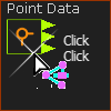
Use a Point FB to measure the motion of a Point* with respect to the Mechanism Plane. It has three output-connectors. From top to bottom, the motion-data at the output-connectors are the: ➔Motion of the Point* parallel to the X-axis ➔Motion of the Point* parallel to the Y-axis ➔Magnitude of the motion equal to: o√(X2 + Y2) Note: Motion includes: Position, Velocity, and Acceleration of the Point*. * Point, start-Point, end-Point, center-Point, Motion-Point. The Point must be a child to a Part that is kinematically-defined. |
Add Point-Data FB
STEP 1: Add a Point-Data FB to the graphics-area
The Point-Data FB is now in the graphics-area (and Assembly-Tree). STEP 2: Open the Point-Data dialog:
|
|||||||
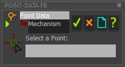
 Point-DATA FB - with no Point |
STEP 3: Select a Point
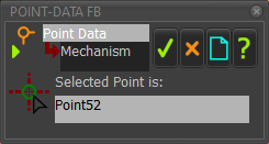
* Point, start-Point, end-Point, center-Point, Motion-Point. The box is now: Selected Point is: |
||||||
 Point-Data FB- with a Point |
STEP 4: Close the Point-Data dialog
The motion-data of the Point is now at the output-connectors of the Point-Data FB. |
||||||
How to use the Point-Data FB:
You can connect a wire from the output-connector of a Point-Data FB:
Note 1: To plot the Position, Velocity and Acceleration of the Point in the same graph. 1.Drag a wire from the same output-connector of the Point-Data FB three times to different input-connectors on a Graph FB, 2.Use the Y–axis display options in the Graph Interface to display the three different motion-derivatives. Note 2: There is a message in the Feedback-Area: '1 Mechanism dependencies detected'. You should Click Rebuild Now when the number of dependencies is more than 1 if the data is critical, before you use the data for a Cam, for example. |
