Gear-Pair
See: Add Gear-Pair
Gear Terminology
Term : |
Definition |
|---|---|
Gear-Wheel (or Gear) : |
A rotating-Part with gear-teeth at a fixed radius from the rotating axis. You control the diameter of the Gear-Wheel with the number-of-teeth and the module. |
Gear-Pair : |
Two inter-locking gear-wheels. Their gear-teeth have External and/or Internal mesh. The angular velocity of each gear-wheel is related by the Number-of-Teeth on each gear-wheel, and the type of mesh (Internal Mesh or External mesh). |
Driving Part : |
The rotating-Part that is kinematically-defined, and whose motion you control (even if it is stationary) before you do Add Gear-Pair. |
Driven Part : |
The rotating-Part whose motion you control by the motion of the Driven-Part, the Number-of-Teeth on each gear-wheel in the Gear-Pair, and the Mesh. |
Gear-Mesh (or Mesh) : |
How gear-teeth inter-lock with each other so that the Gear-Pair can transmit torque and motion from the Driving Part to the Driven Part. |
External Mesh : |
The gear-teeth of the two gear-wheels point outwards from their centers-of-rotation. |
Internal Mesh : |
The gear-teeth of one gear-wheel point inwards towards its center-of-rotation. |
Simple Gear-Pair : |
Two gear-wheels that rotate about two fixed centers. |
Epicyclic Gear-Pair : |
One gear-wheel orbits around the center of the other gear-wheel. |
 Example External Gear-Pair |
Edit the Gear-Pair:
The Gear-Pair dialog is now open. |
Gear-Pair dialog
 Gear-Pair dialog |
There are three tabs in the Gear-Pair dialog. Define tabAdjustments tabParameters tab |
Define tab
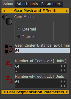 |
Gear Mesh - see Terminology above oExternal OR oInternal Read-only Gear Center-Distance See also center-distance calculation in Adjustments tab Number-of-Teeth, z1 (Minimum =5) The number of-teeth on the input-gear - usually the Driving-Gear Number-of-Teeth, z2 (Minimum = 5) The number of-teeth on the output gear - usually the Driven-Gear |
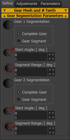 |
Notes: A Gear-Segment must not rotate fully. It must oscillate. Gear # Segmentation ◉Complete Gear - a normal, or full gear ◉Gear Segment - a gear that is not complete, it has fewer teeth. Gear 1 and/or Gear 2 can be a Gear-Segment To reduce the number-of-teeth of Gear 1 and/or Gear 2:
|
Adjustments tab
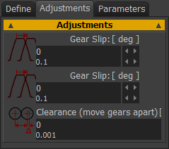 |
Gear-Slip (degrees) These parameters rotate Gear 1 and Gear 2 around at the Pin-Joint. This parameter rotates the gear teeth. It does NOT rotate the Part. I have never used this parameter. Top-Tip: If you add a Gear-Slip to one Gear, then, to keep the gears in mesh: Gear-Slip 2 = – (# Teeth,z1 / # Teeth, z2) × Gear-Slip 1 E.g.: Gear-Slip 1 = 2 degrees, # Teeth, z1 = 120, # Teeth, z2 = 40. Gear-Slip 2 = –(120/40)*2 = –6 degrees. |
Clearance (move gears apart) This parameter changes the length of the Line-of-Centers, the center-distance, between the Gears. Usually, Clearance is a +ve value for External Gears, and a –ve value for Internal Gears. See Notes on recommended backlash. An alternative way to change the clearance is to reduce (by machining) the size of the gear-teeth and not to change the center-distance. We do not have a parameter for this deign option. However, it is the standard method to provide backlash in commercial gear-boxes. Talk with the gear supplier, machinist. Center-Distance Calculation If External Mesh, then center-Distance = Clearance + (Module×(Number-of-Teeth Gear1+Number-of-Teeth Gear2)÷2) If Internal Mesh, then center-Distance = Clearance + (Module×(Number-of-Teeth Gear1-Number-of-Teeth Gear2)÷2) Notes: Recommend Backlash / Clearance. •Minimum: 0.006 × (center-distance)0.5 •Maximum: 0.024 × (center-distance)0.5 Also, I have read that: •Minimum normal backlash = 0.03 × module + 0.05 mm If the torque reverses each machine cycle, then you should aim for the minimum recommended backlash. |
|
Parameters tab
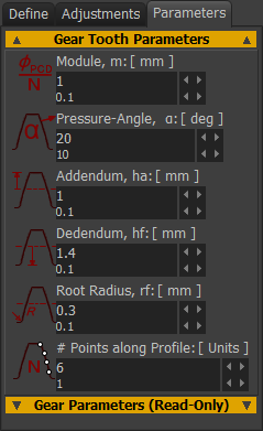 |
Module , m Module, m = P.C.D (in mm) ∕ Number-of-Teeth. If you increase module, the diameter of the Gears increases. The module of the gears in the Gear-Pair are equal. |
Pressure-Angle α - default = 20º Standard gears are 20º. Other standards are: •14º, 17.5º (weaker, quieter), •22.5º and 25º (stronger, noisier). |
|
Addendum, ha - default = m. The radial height of the gear tooth from the Pitch Circle to the top of the tooth. |
|
Dedendum, hf - default = m × 1.25. The radial depth of the gear tooth below the Pitch Circle to the root of the tooth. The Dedendum is usually larger than the Addendum to give a working-clearance for the teeth. If 0.25<m<1, Dedendum is usually = m × 1.4 If m>1, Dedendum is usually = m × 1.25 |
|
Root-Radius, rf - Default is 0.3 × m The small fillet between the Flank and the Root of the Gear Tooth. Note: In reality, if the gear is manufactured from a Hob/Rack Cutter, then the root of the gear is a Trochoid. |
|
# Points along Profile The number of facets and points along the gear tooth flank (and around the two Root Radii). To display Gears more accurately, increase the number of points. Generally, do not increase the number of Points along the Profiles without a good reason. 4 is OK. 10 is accurate, but not usually needed. |
|
 |
For information: Working Clearance = Dedendum - Addendum Working Depth = Addendum × 2 Total Depth = Addendum + Dedendum |
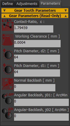 |
ALL READ-ONLY Contact-Ratio: Contact-Ratio should not be less than 1.1. Contact-Ratio should be a minimum of 1.2 for working gears. Working Clearance = Dedendum - Addendum [Note: the units should be [m] not [mm], or let Working-Clearance[mm] = Working-Clearance × 1000] The distance between the top land of a gear tooth and the bottom land of the gear with which is meshed. Gear 1 PCD and Gear 2 PCD PCD = Pitch Circle Diameter. PCD = Module × Number-of-Teeth, (m×z) Normal Backlash (mm) This is the gap (backlash) between the gear-flanks you can measure with a 'feeler gauge'. Normal Backlash is a function of the center Distance Adjustment parameter ONLY. Angular Backlash - Gear 1 (deg) jΘ1 This parameter gives the maximum rotation of Gear 1 if you do not move Gear 2. Angular Backlash is a function of the center Distance Adjustment parameter ONLY. Angular Backlash - Gear 2 (deg) This parameter gives the maximum rotation of Gear 2 if you do not move Gear 1. Angular Backlash is a function of the center Distance Adjustment parameter ONLY. |
Contact-Ratio The Contact-Ratio gives the number-of-teeth that are in contact, on average, as they pass through the meshing point. A contact ratio between 1 and 2 means that contact alternates between one and two pairs of teeth. Gears that have a high contact-ratio are smoother and quieter. The contact-ratio of an Internal Gear-Pair is higher than that of a similar External Gear-Pair. If the Contact-Ratio is too low, then consider these options: •Decrease the pressure-angle •Increase the number-of-teeth •Increase the working-depth |
|
Useful Gearing Calculations and Equations
TO OBTAIN |
FROM KNOWN |
USE THIS FORMULA |
|---|---|---|
Pitch Diameter |
Module, m, number-of-teeth, N |
D = mN |
Circular Pitch |
Module |
pc = m.π = D.π ∕ N |
Module |
Diametrical Pitch, Pd |
m = 25.4 ∕ Pd |
Number-of-Teeth |
Module, m, Pitch Diameter, D |
N = D ∕ m |
Addendum |
Module, m |
a = m |
Dedendum |
Module, m |
b = 1.25m |
Outside Diameter |
Module, m, Pitch Diameter, D, or number-of-teeth, N |
Do = D + 2m = m (N + 2) |
Root Diameter |
Pitch Diameter, D, Module, m |
DR = D – 2.5m |
Base Circle Diameter |
Pitch Diameter and Pressure Angle |
Db = D cos μ |
Base Pitch |
Module, m, and Pressure Angle, μ |
pb = m π cos μ |
Tooth Thickness at Standard Pitch Diameter |
Module, m |
Tstd = π. m ∕ 2 |
Center Distance |
Module, m, number-of-teeth, N |
C = m . (N1 + N2) ∕ 2 |
Contact Ratio for Spur Gears ( 1 < CR < 2 ) |
Outside Radii, Base Circle Radii, center Distance, Pressure Angle |
CR = (√R012 – Rb12 + √R022 – Rb22 – C sin μ) ∕ m π cos μ |
Backlash (linear) |
Change in center Distance, ΔC |
B = 2( ΔC )tan μ |
Backlash (linear) |
Change in Tooth Thickness, ΔT |
B = ΔT |
Backlash (linear) along Line-of-action |
Linear Backlash along Pitch Circle, B |
BLA = B cos μ
|
Backlash, Angular |
Linear Backlash, D |
Ba = 6880 B ∕ D (arc minutes) |
Min. No. of Teeth for No Undercutting |
Pressure Angle, μ |
Nc = 2 ∕ sin2 μ Nc (20º) = ~17 Teeth |
Term |
Definition |
|---|---|
Addendum: |
the height of the gear tooth above the pitch circle diameter |
Backlash: |
the angle the output-shaft of the gearbox can move without the input-shaft moving |
Base Circle: |
an imaginary circle used in involute gearing to generate the involute that forms the tooth profiles |
Bevel Gears: |
used for right-angle applications. There are two types of bevel gears which are straight and spiral |
Center-Distance: |
distance between the axes of two meshed gears - Length of the Line-of centers |
Circular Thickness: |
the thickness of the tooth on the pitch circle. |
Dedendum: |
the depth of the tooth below the diameter of the pitch circle. |
Diametrical Pitch: |
the teeth per inch of the diameter of the pitch circle |
Differential Gear: |
a bevel gear which allows two shafts to rotate at a different speed. |
Gear: |
a wheel with teeth that meshes with another wheel with teeth to translate motion. |
Gear center: |
the center of the pitch circle. |
Gear Train: |
two or more gears meshed by their teeth. A gear train generates power speed through the meshed gears rotating |
Gear Ratio: |
the ratio between the numbers of teeth of meshing gears. |
Helical Gear: |
gear with the gear teeth cut at angles |
Line of Contact: |
the line or curve along which two tooth surfaces are tangent to each other |
Involute: |
the curve which describes a line which is unwound from the circumference of the gear |
Pinion: |
a small cogwheel which fits into a larger gear or track. |
Pitch Circle: |
the curve of intersection of a pitch surface of revolution and a plane of rotation |
Pitch Diameter: |
the diameter of the pitch circle |
Pitch Radius: |
the radius of the pitch circle |
Planetary Gears: |
a system that consists of three components: the sun gear, ring gear, and two or more planet gears. The sun gear is in the center, the ring gear is the outermost gear, and the planet gears are the gears surrounding the sun gear inside the ring gear. |
Pressure Angle: |
the angle between the line-of-action and the normal (90º, perpendicular) to the surface of the tooth |
Spiral Bevel Gears: |
shafts whose axes are perpendicular (90º) to each other and are used in right-angle applications |
Spur Gear: |
connect parallel shafts which have involute teeth that are parallel to the shaft |
Sun Gear: |
a gearwheel that rotates around its own axis and has other gears (planet gears) that rotate around it |
Torsional Strength: |
the measure of the amount of torque that a radial shaft can sustain during its rotation in a mechanical system |
Working Depth: |
the max depth a tooth of one gear extends into the tooth gear of a mating gear |
Worm Gear: |
a gear with one or more teeth with screwed threads |
Image |
Term |
|---|---|
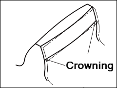 |
Crowning: |
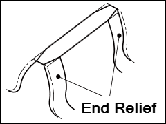 |
End-Relief |
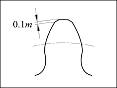 |
Topping and Semi-Topping |
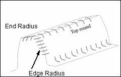 |
End Radius and Edge Radius/End Relief Top Round/Semi-topping
|
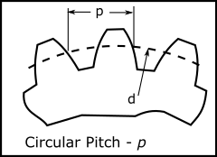 |
Circular Pitch = pitch circle circumference(pi.d) / number of teeth(z) ; p = Π.d / z Module = Pitch Diameter(d) / Number of Teeth(z) ; m = d/z Circular Pitch(p) / Module(m) ; p/m = Π Pitch Diameter(d) = module(m) × number of teeth(z) ; d = m.z
|