Add Bevel Gear-Pair

<< Click to Display Table of Contents >>

Navigation:  MechDesigner Reference & User Interface > 2.2 Mechanism-Editor > Mechanisms > Machine elements >

Add Bevel Gear-Pair

Add Bevel Gear-Pair

See also: Gear-Pair dialog


Add Bevel Gear-Pair and Degrees of Freedom

Add Bevel Gear-Pair removes one(1) degrees-of-freedom.

What is a Bevel Gear-Pair?

When you do Add Bevel Gear-Pair, you add two gears that are in mesh, with intersecting, perpendicular, rotating-axes.

When you do Add Gear-Pair, you add two gears that are in mesh, with intersecting, parallel, rotating-axes.

We find for you the motion of the Driven-Gear from the motion of the Driving-Gear, the number-of-teeth, and the mesh (internal or external).


Kinematics-Tree of Bevel Gear-Pair

Add Bevel Gear-Pair removes one degrees-of-freedom.

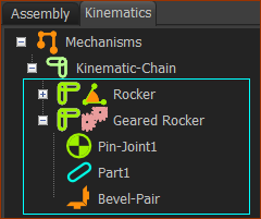
MD-ADD-BEVEL-GEARPAIR-KINEMATICS-TREE

Bevel Gear-Pair

Before you do Add Bevel Gear-Pair, there is a

rotating-Part that is kinematically-defined, and a

rotating-Part that has one degree-of-freedom in a different Mechanism-Editor

After you do Add Bevel Gear-Pair, the rotating-Parts are kinematically-defined.

A Bevel-Pair is a child to the Geared-Rocker.

Prepare Bevel Gear-Pair

To add a Bevel Gear-Pair is more complex than to add a Gear-Pair.

The Parts you add for the two Bevel-Gears are on two different Mechanism-Editors.

The Mechanism-Planes of the two(2) Mechanism-Editors must intersect. They are frequently perpendicular to each other.

Below, for convenience, the names of the two Mechanism-Editors are Mechanism-A and Mechanism-B.

MD-ADD-BEVELGEAR-0

Preparation A1: Mechanism A

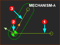
LineRed-14-1 and LineRed-14-3 are in Parts that are kinematically-defined

LinesRed-14-1Red-14-2 are joined with a Pin-Joint

LineRed-14-2 has a dimension (in the Part-Editor)

See MD-Globe-www Tutorial 1: Add a Rotating-Part.

Preparation A2: Add a Plane to the Line in the Base-Part

1.Click Mechanism menu or Model elements toolbar > Add Plane

2.Click the LineRed-14-1 in the Base-Part

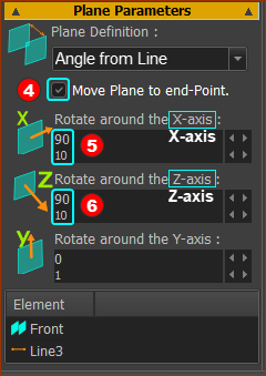
In the Add Plane dialog:

1.Enable Move Plane to end-PointRed-14-4

2.Enter 90º in the Rotate around the Z-axisRed-14-5

3.Enter 90º (default value) is in Rotate around the x-axisRed-14-6.

See MD-Globe-www Tutorial 1: Add a Rotating-Part.

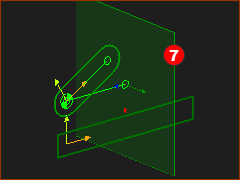
New Plane for Mechanism-B

New Plane for Mechanism-B

MD-BEVEL-ADDPLANE-MOVEPLANE

MD-BEVEL--02

MD-BEVEL--03

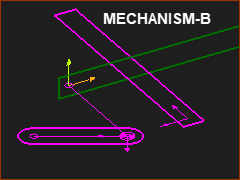
Preparation A3: Add Mechanism-B to the new Plane

1.Click Mechanism menu or Model elements toolbar > Add Mechanism-Editor

2.Click the new PlaneRed-14-7

You jump to the new Mechanism-Editor - Mechanism-B


A) Enable Visibility toolbar > Show other Kinematic and Sketch elements

AND

B) Right-click the Mechanism name-tabs Light-Bulb > Enable Show with other Kinematic and Sketch-Elements

C) Spin the model to show the other kinematic and sketch-elements


Preparation B1: Add a new Part and Pin-Joint

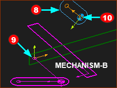
1.Click Kinematic elements toolbar > Add Part | Drag to add the PartRed-14-8

2.Click Kinematic elements toolbar > Add Pin-Joint

a.Click the start-Point of the new PartRed-14-10a

b.Click the end-PointRed-14-9 of the Line in Mechanism-A


The Pin-Joint does not move the Points together. The PartRed-14-8 moves to a new place!!!

See also: Geared-Rocker, Dyads and Kinematics-Tree

Add Bevel Gear-Pair

MD-ADDBEVELGEAR--01

Note: Click Mechanism-A to make it the active Mechanism-Editor.

STEP 1: Click Add Gear-Pair

MD-Icon-AddGearPair

1.Mechanism menu > Add Gear-Pair

or

1.Machine-elements toolbar > Add Gear-Pair

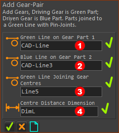
There are four elements to select in the Command-Manager.


STEP 2: Select the four elements

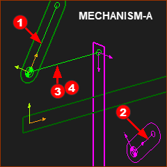
Red-14-1 The Line along the center of the rotating-Part in Mechanism-A

Red-14-2 The Line along the center of the rotating-Part in Mechanism-B

Red-14-3 The Line in Base-Part

...

MD-ADDBEVELGEAR--CM-02

MD-ADDBEVELGEAR--GA-02

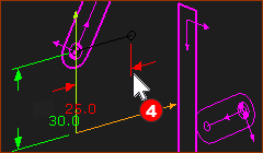
The Part-Editor opens to show LineRed-14-3 and its dimensionRed-14-4.

...

Red-14-4 Click the arrowhead, or the dimension line.


STEP 4: Complete the Command

Click OK-tiny-11-15 in the Command-Manager.

Result:

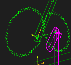
The Bevel Gear-Pair is in the graphics-area.

The default Bevel Gear-Pair has an External Mesh and the gears have an equal number-of-teeth.

All Parts are kinematically-defined.

Bevel Gear Part is in the Kinematics-Tree as a Geared-Rocker.

To edit the Bevel-Gear-Pair parameters: see Gear-Pair dialog

MD-ADDBEVELGEAR--GA-03