Add Pulley
See also : Pulley dialog
Pulley / Belt Terminology
Term : |
Definition |
|---|---|
Pulley : |
When you do Add Pulley, we add for you the outline of a Pulley, with teeth, to a rotating-Part - see below, Types of Pulley The rotating-Part of a Pulley must rotate about the center-Point of an Arc that is on the sketch-path of a Belt. |
Belt : |
A sketch-path to represent the path of the Belt, with a Motion-Path FB to control the motion of a Motion-Point along the sketch-path, to represent the motion of the Belt. |
We relate the angular motion of each Pulley to the linear motion of the Motion-Point on a Belt by the radius of each Pulley. To control the radius of each Pulley, you can edit the Pulley to control its number-of-teeth and/or edit the Motion-Path FB to control the Tooth-Pitch of the Belt. |
|
Types of Pulley
You can do Add Pulley to a rotating-Part that is kinematically-defined (Type 1) or a rotating-Part that is not kinematically-defined (Type 2). |
|
Type 1: A Driving-Pulley : |
Before you do Add Pulley, the rotating-Part is kinematically-defined. After you do Add Pulley, we control the linear motion of a Belt from the angular motion of the rotating-Part (Driving-Pulley). Add a maximum of one Driving-Pulley to a Belt. |
Type 2: A Driven-Pulley : |
Before you do Add Pulley, the rotating-Part is not kinematically-defined. After you do Add Pulley, we control the angular motion of a rotating-Part (Driven-Pulley) from the linear motion of the Belt. |
Kinematics-Tree of Pulley
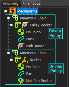 |
Driven-Pulley
|
|
Driving-Pulley
|
Prepare to Add Pulley (TYPICAL)
STEP 1: Add the sketch-path for the Belt.
 Sketch-loop as the path of the Belt. |
STEP 1: Add a sketch-path to represent the path of the Belt.
If the rotating-Part is a Rocker for a Driving-Pulley (see also STEP 3A)
Why? You need the Line to add a Motion-Dimension FB to the rotating-Part. |
||
 A Line for a Motion-Dimension FB |
STEP 2: Add the Motion-Path FB to the sketch-path
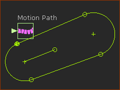 |
STEP 2: Add a MOTION-PATH FB Add ONE Motion-Path FB to the sketch-path.
The Motion-Path FB is in the graphics-area. There is a Motion-Point at the start-Point of the sketch-element you click. |
STEP 3: Add a Rotating-Part for a Pulley
A Pulley is a Driving-Pulley or Driven-Pulley. It is a rotating-part.
STEP 3A: Type 1 - Driving-Pulley |
||
 rotating-Part for a Driving-Pulley |
A Driving-Pulley is a rotating-Part that is kinematically-defined before you do Add Pulley. Add a maximum of ONE Driving-Pulley to a Belt.
|
|
STEP 3b: Type 1 - Driven-Pulley |
||
 rotating-Part for a Driven-Pulley |
A Driven-Pulley is a rotating-Part that is not kinematically-defined before you do Add Pulley.
The motion of the Belt and the Pulley's Pitch-Circle Diameter control the motion of a Driven-Pulley. |
Add Pulley
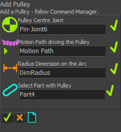 |
STEP 1: Click Add Pulley
There are four elements to select in the Command-Manager STEP 2: Click the four elements
* If the rotating-Part is : •is kinematically-defined - the motion of the Pulley moves the Belt (Driving-Pulley). •is not kinematically-defined - the motion of the Belt moves the Pulley (Driven-Pulley). STEP 3: Complete the Command
Result:
|
|||||
 1 x Driven-Pulley (Magenta)") 1 x Driving-Pulley (Purple) Do Add Pulley to add 1 x Pulley. The image shows two Pulleys after you do Add Pulley two times. |
Video: Add Pulley:

Video: Add Pulley (and the Belt-Path)