Motion-Path FB
When you add a Motion-Path FB, we add a Motion-Point to the sketch-element you select.
Motion-values at the input-connector to a Motion-Path FB control the motion of a Motion-Point along a sketch-path/loop.
The data-type of the motion-values at the input-connector also control the motion of the Motion-Point along the sketch-path/loop.
The data-type should be Linear or Rotary - see also Motion FB dialog
When the data-type at the input-connector is:
•Linear(mm) : the displacement of the Motion-Point is equal to the Linear motion-value at the input-connector
•Rotary(degree) : the displacement of the Motion-Point is equal to the Rotary motion-value × total length of sketch-loop / 360
Optionally, use the Motion-Path dialog to control and specify the length of a sketch-path or sketch-loop - typically a belt.
See more: Data-Type and Motion-Points
|
To open the Motion-Path dialog
|
|
The Motion-Path dialog is now open. |
||
 Motion-Path dialog |
There are usually two tabs: Point ParametersLength ControlIf a Transition-Curve is a sketch-element in the sketch-path/loop, you will see three tabs. Transition-Curves |
Point Parameters tab
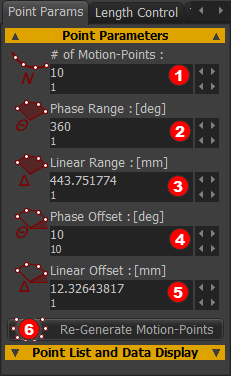 |
To edit the number of Motion-Points along the sketch-path/loop.
Edit the Phase Range / Linear Range to distribute Motion-Points (when # Motion-Points > 1) over a range (length) that is different to the total-length of the sketch-path.
|
|||
Example for Phase Range and Linear Range We urge you to experiment.
|
||||
Phase Offset (deg) Linear Offset (mm)
Example - for Phase Offset and Linear Offset We urge you to EXPERIMENT.
|
||||
|
||||
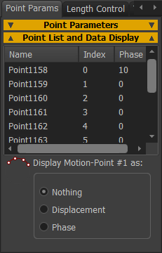 |
Headers: Name | Index | Phase (read-only) •Name : the element-name of each Motion-Point. If you click on a Motion-Point in the list, it shows as the Selected-Color in the graphics-area. •Index : the number of the Motion-Point •Phase : the relative phase along the sketch-path, relative to the Motion-Point #1 Note: As you edit the Point Parameters, the Phase data lags one 'click' from the actual phase. You can open and close the dialog to show the correct Phase. Display Motion-Point #1 as You can show the position/phase of Motion-Point #1 from the start-Point of the sketch-path as it moves along the sketch-path. ◉Nothing - show nothing near to the Motion-Point #1 ◉Displacement - the linear position shows near to Motion-Point #1 ◉Phase - the angular phase shows near to Motion-Point #1 |
Length Control tab
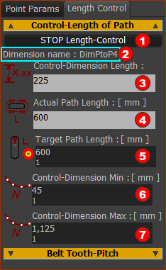
You can select a dimension to control the length of the sketch-loop that you associate with the Motion-Path FB. We use the term Control-Dimension for the dimension you select- see Note 1 Important
|
|||||||||||||
 |
To control the length of the Motion-Path with a Dimension:
When you do not want to control the length of the Motion-Path with a dimension:
|
||||||||||||
Note 1: Rules for Control-Dimension The Control-Dimension must be:
The control-dimension Must Not be:
|
|||||||||||||
Parameters
Target Path Length
Control-Dimension Min
|
|||||||||||||
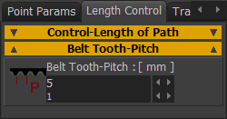 |
Belt-Tooth-Pitch The Belt-Tooth-Pitch does not change the belt length. The diameter of a Pulley is a function of the number of teeth AND Belt Tooth-Pitch. See Pulley dialog |
Note 2: Target Path-Length Edit the Target Path-Length with small increments. If the Actual Path Length does not change, see Note 3 Note 3: Control-dimension minimum and/or Control-Dimension Maximum If the Actual Path Length does not change, you may see the message in Feedback-Area (below the graphics-area)  The default values of Control-Dimension Min and Control-Dimension Max bracket the Control-Dimension so that the Actual-Path Length can equal the Target Path Length. However, it is possible that the Root-Finding Math to calculate the Control-Dimension and the Actual-Path Length is confused! To reset the Root-finding Math: •Increase or decrease the Control-Dimension Min/MAX, then try to edit the Target-Path-Length again. You may need to edit the Control-Dimension Min and Max values to be almost equal to the actual length of the Control-Dimension. |
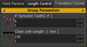 |
This tab shows when there is one or more Transition-Curves in the sketch-loop. # Sprocket Teeth Maximum = 11 ; Minimum = 3 Chain Link-Length When the Target Path Length is set (see Length Control tab), you can enter the Chain-Link Length to give an integer number of teeth. |
MOTION-PATH AND DATA TYPES
The position and motion of Motion-Points along the sketch-loop is a function of the Data-Type at the input-connector to the Motion-Path FB. The Data-Type at the input-connector must be Linear or Rotary. Data-Type = Linear
Data-Type = Rotary
|