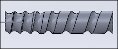
What is a scroll?
A Scroll feeds products, typically bottles or cans, into a Rotating Machine. The products are in a buffer as they move into the start of the Scroll. At the end of the scroll, the products move into a star-wheel. The star-wheel feeds the products into a rotating machine.
The pitch of the products in the buffer, at the start of the scroll, is the same as the length of the product. The products are moved apart by the scroll until their pitch is the same as the pockets in the star-wheel, that is at the end of the scroll. The pitch of the products on the star-wheel is the same as the pitch of the products on the Rotary Machine.
Other names for a Scroll are: Feedscrew, Worm.
Add Scroll
|
Machine Elements toolbar > Add Scroll |
Menu : |
Add menu > Mechanism sub-menu > Add Scroll |
What to do : |
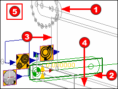
You must do the Preparation before you can do Add Scroll. You need five elements: 1.A Part for the moving 'Pack'. A sketch-loop is the cross-section of the 'Pack'. You must also add a Motion-Path FB (see 5) and generate a number of Motion-Points to the sketch-loop. 2.A Part that is the rotating Scroll. 3.A sketch-loop and Profile that is the cross-section of the Scroll. 4.A Line to be the Scroll's axis-of-rotation. 5.A Motion-Path FB. |
Result : |
A Scroll in the graphics-area. |
Preparation : |
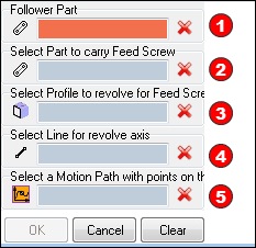
There is a significant amount of preparation. You must prepare five elements in 2 Mechanism-Editors. See Preparation When you click Add Scroll, you see five selection-boxes in the Command-Manager. |
Preparation for 'Add Scroll'
STEP 1: Pack: Shape; Motion, and Motion-Points
The Pack moves along a line that is parallel to the scroll's rotation-axis. It is also possible to rotate the Pack on its own axis as it moves from the entry to the exit of the scroll. |
|
|
1.Add a Mechanism to a 'Plane' - the 'Front' Plane - in the Model-Editor. 2.Rename the Mechanism-Editor to 'Pack'. In the new Mechanism-Editor: 3.Add a Slider with a motion to define the axial motion of the Pack If the Pack rotates as it moves along the scroll: 4.Add a Rocker to the Slider Part, and a motion to define the rotation of the Rocker / Pack 5.Then add the shape of the Pack to the Slider or Rocker. The shape of the Pack must be a sketch-loop. If the Pack is not prismatic, then the shape should represent the its cross-section at the height of the scroll's rotational-axis. |
The Motion for the Axial and Rotation of the Pack |
|
 Click to Expand and Collapse |
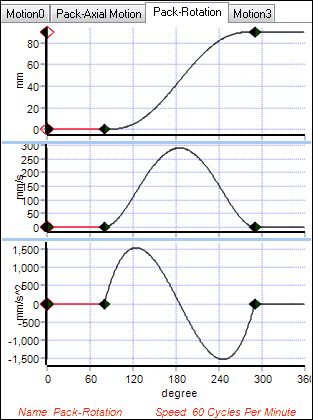
Pack Axial Motion The motion usually has a 'Constant Velocity Segment' as its first and last segment. Thus, there are two(2) Velocities you must consider. Start Velocity, (SV) Packs are usually adjacent '(bunched up', 'back-to-back') SV = Product-Length ÷ Time for scroll to rotate one time Final Velocity, (FV) Packs should be at the same pitch as the star-wheel or circular pitch of the Rotary Machine FV = Rotary Pitch ÷ Time for scroll to rotate one time 'Time', or 'Number of Machine Degree', for Scroll to rotate one time. This is a function of the number-of-times the scroll rotates. Thus, of the length of the Scroll The first constant velocity is the speed of the bottle at its entry. The last constant velocity is the speed of the bottle at its exit. You need to edit the motion later. |
|
Pack Rotation The Pack rotates by 90º as it moves from the entry to the exit. The duration of the segment that rotates the pack is the same duration as the segment that accelerates the pack.
|
Motion-Path, Motion-Points. |
|
|
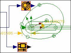
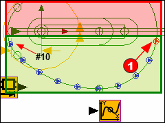
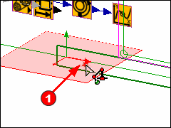
In order to calculate the shape of the scroll, you must define the contact between the Pack and the Scroll. Rather than a Profile, you add Motion-Points to the shape of the Pack. Each Motion-Point define a 'Rim' along the scroll - as you see. 1.Click Add Motion-Path 2.Click one of the sketch-elements that give the shape to the Pack One Motion-Point |
|
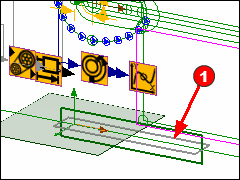
1.Double-click the Motion-Path FB to open the Motion-Path dialog 2.Edit the '# Motion-Points' to 10 - we can edit this number later, if necessary. 3.Click the 'Re-generate Motion-Points'. 4.Edit the 'Range' of the Motion-Points to 160º (use the Range option in degrees). 5.Edit the 'Base-Value' of the Motion-Points until they are only in the half of the sketch-loop for the Pack that 'faces' the rotation-axis. The Motion-Points must be in the 'Green Area' The Motion-Points cannot be in the 'Red Area'. |
A Motion for the Motion-Points |
|
|
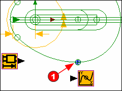
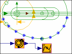
As the Pack rotates, we must also rotate the Motion-Points in the opposite direction so that they remain in the half of the Pack that faces the rotation-axis. 1.Connect a wire from the output-connector of the Motion-Dimension that rotates the Pack to the input-connector of the Motion-Path. You may need to add a Gearing FB, with a ratio of -1, to move the Points in the opposite direction. |
STEP 2: Add the Scroll rotation-section and its rotation-axis.
|
(Note: I have rotated the Pack by 180º on the rotating Part. This helps later) We must add a sketch-loop that represents the rotation-section of the scroll. 1.Edit the Base-Part 2.Click Visibility toolbar > Show/Hide other Kinematic and Sketch elements - this shows the shape of the Pack 3.Add a rectangle The rotation-section needs a rotation-axis. 4.Add a Line This should be along the X-axis of the Base-Part. |
|
We must also add a Profile to the rotation-section 1.Close the Part-Editor 2.Add a Profile When we send the rotation-section and rotation-axis to SolidWorks, SolidWorks makes a 'revolved-section'. |
STEP 3: Add a Plane, Mechanism, add the Scroll Part
We add the scroll in a different Mechanism-Editor. We must add a new Plane for the new Mechanism-Editor. The Plane to which we add the new Mechanism-Editor must be orientated in a particular direction. If the Plane is not in the correct orientation, we cannot add the scroll. |
|
Add the new Plane |
|
|
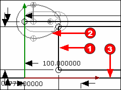
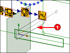
1.Spin the model with your keyboard arrow keys 2.Click Add Plane 3.Click the arrowhead of the X-axis at the Origin of the Base-Part (you can also click the Y-axis) The image shows the default position of the new Plane. We must use the Add Plane dialog to re-orientate the Plane. It is possible to use the Add Plane dialog to edit the orientation of the new Plane now. However, I find it easier to 'Add a new Mechanism' to the Plane now, and then edit the Plane for the new Mechanism later. |
|
4.Close the Add Plane dialog 5.Click Add Mechanism 6.Click the new Plane 7.Click OK in the Command-Manager You 'jump' to the new Mechanism-Editor. Rename the new Mechanism-Editor to 'Scroll' 8.Click the 'Pack' Mechanism name-tab to return to the Pack Mechanism-Editor. 9.Click Tools menu (or toolbar) > 'Show Sketches in Mechanism' You can now see the new Plane and the Base-Part |
|
10. Edit the new Plane - double-click it to open the Plane dialog MechDesigner Rules - relative orientation of the new Plane with respect to the orientation of the Pack's Mechanism Plane. •The Z-axis of the Scroll Mechanism's Base-Part must be co-axial with the X-axis of the Pack Mechanism's Base-Part •The Y-axis of the Scroll Mechanism's Base-Part must be co-axial with the Y-axis of the Pack Mechanism's Base-Part If you clicked the X-axis to add the new Plane, then the X, Y and Z-axis rotations are 90,90,90 respectively. If you clicked the Y-axis to add the new Plane, then the X, Y and Z-axis rotations are 0,90,90 respectively. The image shows the new orientation of the Base-Part and Mechanism-Plane of the 'Scroll' Mechanism. |
|
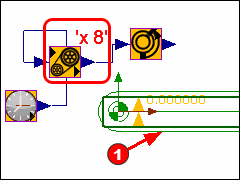
11.Click the Scroll Mechanism name-tab We now add the Part that represents the 'scroll'. 12.Add a rotating Part Make sure the Origin of the Part is at the Origin of the Base-Part. Add a Gearing FB, and edit its Gearing Ratio parameter so that the Scroll Part rotates many times in a machine-cycle. I suggest a Gearing Ratio of 'x8' as the first estimate. |
|
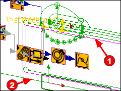
13.Click ALT+H keyboard shortcut to Home the model, in which the MMA is at 0 14.Rotate the view so you can see the elements in the two(2) Mechanism-Editors. 15.Click Add Scroll. |
|
Select the five elements in order.
Click OK
|
|
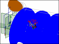
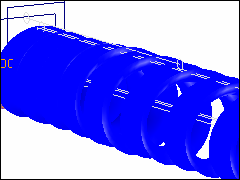
You may need to click the Model-Editor to force a full model rebuild. MechDesigner creates a surface for the part of the scroll that becomes in contact with the Pack, as the Pack advances.
|
STEP 4: Transfer the Scroll to SOLIDWORKS
|
To transfer the Scroll to SOLIDWORKS, we need to edit the Scroll element. 1.Double-click the Scroll in the graphics-area or 1.Double-click the Scroll element in the Assembly-Tree
|
|
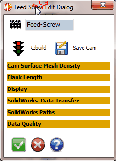
The Scroll Element dialog (Also called the Feed Screw - dialog). The important separators are: Cam (that is: Scroll) Surface Mesh Density •Edit the number of Points along each Rim. •Typically 500 to 1500. Flank-Length The Flank Length is with respect to the MMA. •Typically, set to 0 to 360 Display •color •Transparency - applies to view in the Model only •Show as Solid (Surface) and Rims check-boxes. |
|
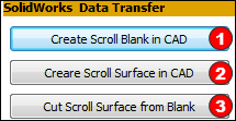
SOLIDWORKS Data Transfer 1.Start SOLIDWORKS, add a new Part, and Save it. 2.You can click each button in turn |
|
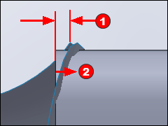
If the Scroll Surface is not cut from the Scroll Blank, there may be a couple of things you should look at. 1.The end of the Scroll Surface is outside the ends of the Scroll Blank. In the image, you can see that the Scroll-Blank extends past the start of the Scroll Surface. Edit the Scroll-Blank in SOLIDWORKS or MechDesigner. 1.Move the left end of the sketch to the right by a small amount. |
|
When the Scroll Surface is cut from the Blank, then hide the Scroll Surface. |