Slide-Joint
 Slide-Joint in MechDesigner |
 Slide-Joint - THK |
 Slide-Joint in SOLIDWORKS |
Terminology
Slide-Joint : |
A Slide-Joint forces a Line* in a Part to be collinear with a Line* in a different Part. A Slide-Joint removes two degrees-of-freedom from the model. A Slide-Joint lets the two Parts move relative to each other with a rectilinear translation motion. * Line or CAD-Line. |
Prismatic Joint : |
The kinematic term for a Slide-Joint. |
Kinematics-Tree : |
The Slide-Joint is a: Slider: is a sliding-Part whose linear position you control with a Motion-Dimension FB. P - the letter we use to represent a Slide-Joint when it is one of three joints in a Dyad - for example: P-R-P dyad. |
Derived Names: |
|
sliding-Part : |
A Part that you join with a Slide-Joint to a different Part. |
A Slide-Joint in the graphics-area
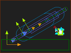
 Slide-Joint |
The symbol for a Slide-Joint the graphics-area:
* The Positive-Direction is the direction in which the Part moves if you also add a Motion-Dimension FB to the Slide-Joint to give a Slider. See Positive direction of Slide-Joints and Motion-Dimension. |
|
IMPORTANT: To calculate reaction Forces on a Slide-Joint: The length and position of the Lines should be the actual length and position of the Slide-ways and Slide-Blocks. |
||
Add Slide-Joint:
 Select two Lines A New Slide-Joint |
STEP 1: Start the Add Slide-Joint command
STEP 2: Click the two(2) Lines
The two(2) Lines are collinear at the Slide-Joint. The Positive Direction of the Slide-Joint is identified by the small arrowhead at the start-Point of Line If the Select-Elements dialog opens, see Slide-Joint Special Case
|
VIDEO: Add Slide-Joint - Simple-Case

Video: Add Slide-Joint - Special-Case
Special Case: two(2) or more collinear Slide-Joints
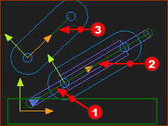
Frequently, a machine design has two(2) collinear Slide-Joints between three Parts. You must decide which two(2) Lines from which two(2) Parts you want to select for each Slide-Joint. For example: There are a total three Parts. You must add two(2) Slide-Joints: Slide-Joint#1 - joins Line 1 and Line 2 (in Part 1 and Part 2), Slide-Joint#2: joins Option A: Line 3 and Line 1 (in Part 3 and 1Part ) or Option B: Line 3 and Line 2 (in Part 3 and Part 2) Option A or Option B is important when you also must add a Motion-Dimension FB to control the motions of each Part. |
||||||
|
Preparation example:
|
|||||
|
STEP 1:Add Slide-Joint
STEP 2:Select two(2) Lines:
|
|||||
|
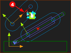
You have clicked a total of three Lines. However, the Slide-Joint is between two Lines. Therefore, there is ambiguity. Which two Lines do you want for the Slide-Joint? “Ambiguity” : when MechDesigner does not know which elements you want to select. |
|||||
|
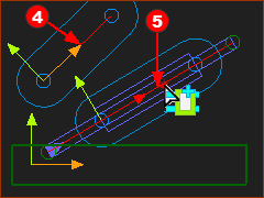
When there is ambiguity, the Select Elements dialog opens. <<< Select-Elements dialog
|
|||||
 Two Lines are Compatible |
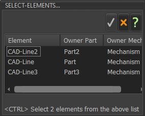
STEP 3:Select the TWO Lines in the Select-Elements dialog
You can select:
You cannot select:
Why not CAD-Line and CAD-Line3 ?
|
|||||
 Two Lines are Compatible |
||||||
 Two Lines are NOT Compatible |
||||||
|
STEP 5: Close the Select-Elements dialog
There are now two(2) Slide-Joint between three(3) Lines |
|||||