Part
See also: Edit Part
Part Images
 Part in MechDesigner |
 A Part in SOLIDWORKS |
 A physical part/link |
Terminology
Part : |
Parts you add to the model, They represent fixed or moving components in a machine. There is a CAD-Line from the start-Point and end-Point, which is the length of the Part when you add it to the model. Use the Part-Editor to edit the length of the Part, add sketch-elements, dimensions, and/or geometric constraints. |
Base-Part : |
The Part we add for you when you add a Mechanism-Editor. Note: a Mechanism-Editor moves with a Part when you add a Mechanism-Editor to a Plane to a moving Part. |
Part-Outline : |
The Part-Outline is the symbol for a Part. Part-Outlines have three shapes: •Oval: the shape that wraps around the start-Point and end-Point of the CAD-Line when you add it to the model •Rectangular: symbol of the Base-Part New MD17-1-168: •Rounded Polygon: the shape that wraps the CAD-Line and all joints made with the Part |
A Part has two possible kinematic-states. |
|
Not kinematically-defined : |
The state of a Part when it has one or more degrees-of-freedom. Other terms: Free-Part, Completely-Free Part, a Part that is not solved. The color of the Part-Outline is approximately Blue (usually) |
kinematically-defined : |
The state of a Part when its Mobility is Zero(0). Other term: is a Part that is solved. The color of the Part-Outline is approximately Green (usually) |
IMPORTANT: All of the Parts in your model must be kinematically-defined before you can analyze kinematic (motion) and kinetostatic (force) data in your model. |
|
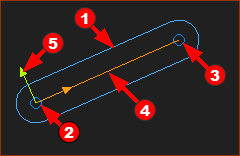
A Part in the graphics-area.
 |
|
|
Note:
|
||
Add Part
 DRAG to add |
STEP 1.Start the Add Part command
STEP 2.Add the Part The Part is now in the graphics-area. The symbol for the Part is the oval Part-Outline, which wraps around CAD-Line between the start-Point and end-Point of the Part.
|
||||
 Added Part, as Oval Part-Outline |
|||||
 MD17-1-168+: Part-Outline in the shape of a 'Rounded-Polylgon'. |
New: MD17-1-168 + If you add Joints to the Part, the Part-Outline wraps around the CAD-Line and also the Points and Lines associated with the Joint. |
Video:

Video: Add a Part