Motion-Dimension FB
See also: Motion-Dimension dialog
Terminology
Motion-Part : |
A Part whose angular or linear position and motion relative to a different Part you control with a Motion-Dimension FB. |
Rocker : |
A Motion-Part that rotates. |
Slider : |
A Motion-Part that slides. |
Motion-Dimension FB : |
Add this Function-Block to a Part that has one degree-of-freedom to change it to a Motion-Part: Rocker or Slider. |
Base-Value : |
The parameter we use to offset the Motion-Part. |
 Add Motion-Dimension FB - ROCKER
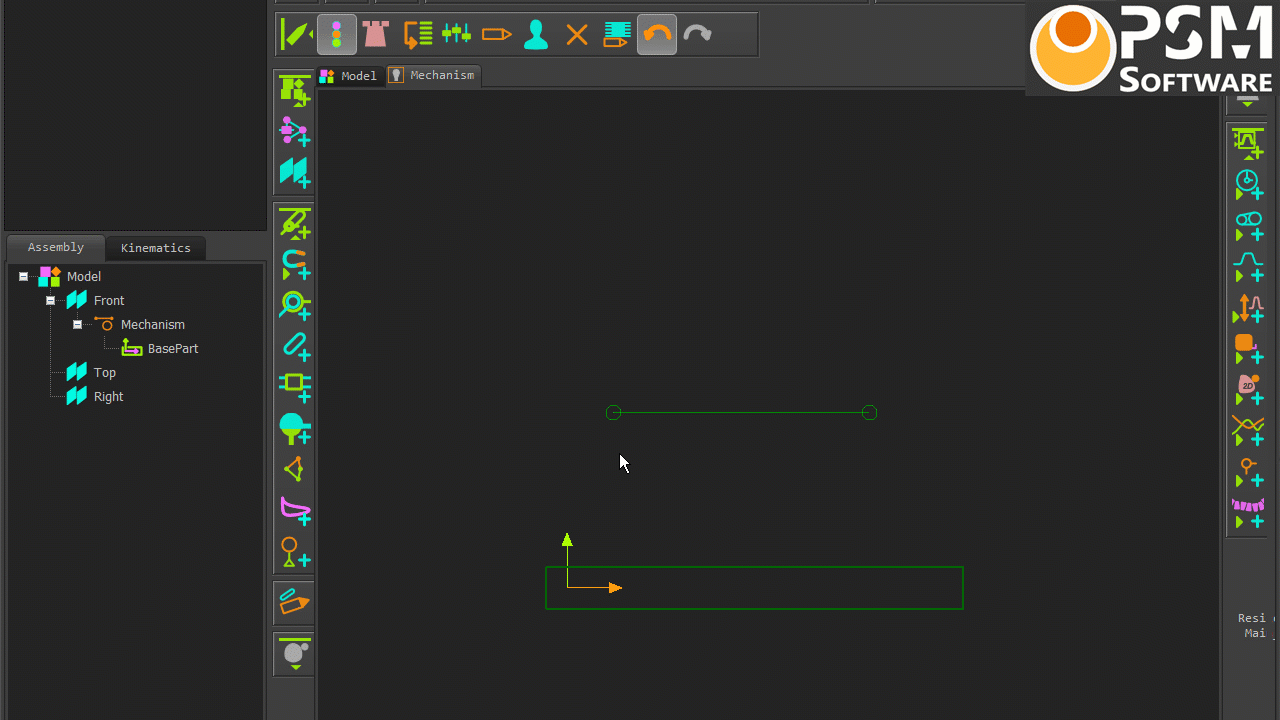
Prepare the model with these elements.
|
|||||||||||||||
Preparation: Motion-Dimension - Rocker (typical)
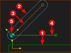 |
Preparation example: •Two(2) Parts. In this case the Base-Part •Lines •Pin-Joint •Part •Part See Add Line, Add Part, Add Pin-Joint |
Add Motion-Dimension FB (Rocker)
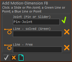 |
STEP 1: Select the Add Motion-Dimension FB command
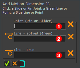
The Command-Manager indicates that there are three elements to select: |
|||
 |
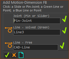
STEP 2: Select the three elements in the graphics-area
STEP 3: Complete the Command
|
|||
 |
||||
Result: |
||||
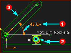 |
The Mobility of the kinematic-chain is now Zero(0).
Note: In the graphics-area: •To move the Motion-Dimension •To move the Motion-Dimension FB |
|||
Dialog : |
STEP 3: Open the dialog - See Motion-Dimension dialog |
|||
Kinematics-Tree - Motion-Dimension (Rocker)
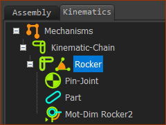 |
When you add a Motion-Dimension FB to a Pin-Joint, you add a Rocker to the Kinematics-Tree. The kinematic elements are: Part + Pin-Joint + Motion-Dimension = ROCKER |
 Add Motion-Dimension FB and SLIDER
Prepare the model with these elements.
|
|||||||||||||||
Preparation: Add Motion-Dimension - Slider (typical)
|
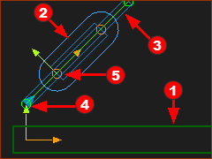
Preparation example:
See Add Line, Add Part, Add Pin-Joint |
Add Motion-Dimension FB (Slider)
|
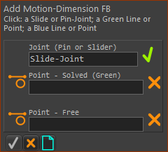
STEP 1: Add the Motion-Dimension FB
|
|||||
|
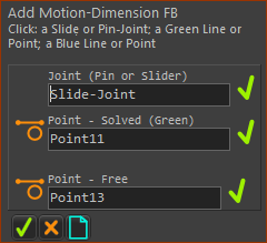
STEP 2: Select three elements in the graphics-area
STEP 3: Complete the Command
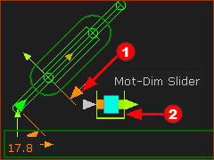
Result :
Note: In the graphics-area: •To move the Motion-Dimension : CTRL + Drag the FB icon •To move the Motion-Dimension FB : Drag the FB icon STEP 4: Open the dialog - See Motion-Dimension dialog |
|||||
|
||||||
|
Kinematics-Tree - Motion-Dimension (Slider)
|
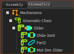
When you add a Motion-Dimension FB to a Slide-Joint, you add a Slider to the Kinematics-Tree. The kinematic elements are: Part + Slide-Joint + Motion-Dimension = SLIDER |
Videos: Add Part, Add Joint, Add Motion-Dimension FB:
Add Motion-Dimension FB to a Pin-Joint
Video: Add Motion-Dimension FB - Rocker
Add Motion-Dimension FB to a Slide-Joint
Video: Add Motion-Dimension FB - Slider
Special Methods
Frequently, in a machine, Pin-Joints can be coincident (co-axial) and Slide-Joints can be collinear.
There are two or more rotating-Parts that rotate about one center, or two or more sliding-Parts that slide along one axis.
Special Method: Coincident Pin-Joints
If you want to control the motion of each rotating-part with a different Motion-Dimension FB, you must carefully plan as to which Points you select when you add the Pin-Joints.
Then, when you add the Motion-Dimension FBs, the Motion-Dimensions can reference the correct Parts.
The Points you select when you add the Pin-Joints determine between which two Parts you can add the Motion-Dimension FB.
Special Method: Coincident Slide-Joints
If you want to control the motion of each sliding-part with a different Motion-Dimension FB, you must carefully plan as to which Lines you select when you add the Slide-Joints.
Then, when you add the Motion-Dimension FBs, the Motion-Dimensions can reference the correct Parts.
The Lines you select when you add the Slide-Joints determine between which two Parts you can add the Motion-Dimension FB.
Special Method 1
The methods and principles described below apply to Rockers and Sliders. However, the descriptions below are given for Rockers only.
|
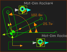
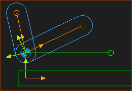
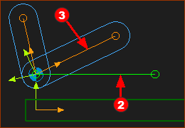
Result of Special Method 1: The model shows •Two Motion-Dimension FBs •They reference the same Line in the Base-Part. You can see the dimension of the two Motion-Dimensions FBs reference and start at the horizontal green Line. |
|
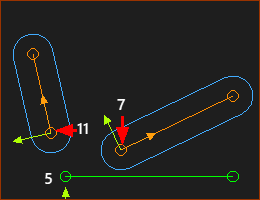
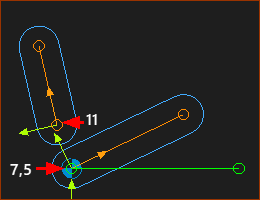
There are two added Parts There is an added Part. As always, it has a CAD-Line, with a start-Point and an end-Point. There is also Line. This Line is in the Base-Part, which you cannot see. There are three(3) Lines in three(3) Parts in total. The start-Points of the lines are 5, 7 and 11. Note: You can select the start-Points and/or the end-Points. However, when possible, use the start-Points. |
|
|
Add Pin-Joint #1 In the image to the left, Pin-Joint #1 is between point 7 and 5 Now, add a Pin-Joint. #2 ADD Pin-Joint #2 Add Pin-Joint #2 between Points 11 and 5. Q: Why Points 11 and 5 and not 11 and 7 ? A: You want the Motion-Dimensions to reference the horizontal Line in the Base-Part. |
|
|
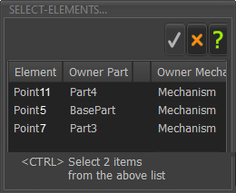
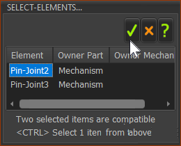
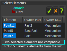
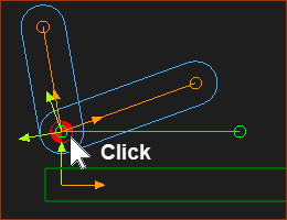
Add Pin-Joint : 1.Click Point 11 and then try to click Point 5. The Select-Elements dialog opens! Why? Because there is ambiguity. Points 5 and 7 are at the same position. You have actually clicked three Points (11, 7 and 5). You must select the two Points for the Pin-Joint.
|
|
|
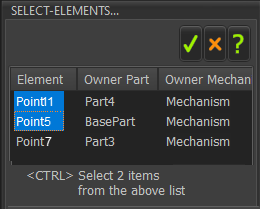
2.CTRL + Click ALL of the elements you need to complete the command.
In this image, select Point 11 and Point 5 1.CTRL + CLICK Point11 AND Point5 2.Click
|
|
|
Now, the two Parts are joined with a Pin-Joint to one Point in the Base-Part. |
|
The two Parts are now joined to the Base-Part with two Pin-Joints Now, use the Motion-Dimension FB two times Add Motion-Dimension 1 1.Click Function-Block toolbar > Add Motion-Dimension FB. |
|
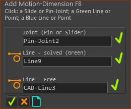
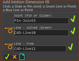
The Command-Manager show that you must select three elements
The first-element must be a Pin-Joint or Slide-Joint. There are two Pin-Joints! |
|
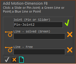
When you click the Pin-Joints in the graphics-area the Select-Elements dialog opens as there are two Pin-Joints. In the Select-Elements dialog: Click the Pin-Joint. |
|
|
|
Now, select two Lines.
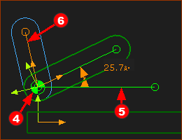
Click the horizontal Line Click the CAD-Line |
|
This image shows the three elements in the Command-Manager boxes. |
|
The first Rocker Motion-Dimension FB.
Add Motion-Dimension #2
You must now select another three elements, |
|
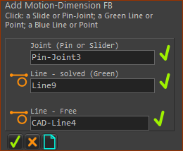
Function-Block Toolbar > Motion-Dimension FB again. These are the elements.
Now, there is no ambiguity. There is only one Pin-Joint available.
|
|
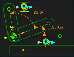
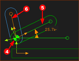
Here, you can see the result. Both Motion-Dimensions FBs use the Horizontal Line in the Base-Part as a reference for the motion-dimension. Note: When you add two Motion-Dimensions, the FBs may be on top of each other. Drag each FB so you can see them. |
Special Method 2:
|
Result of Special Method 2 •Motion-Dimension 1: From the Line in the Base-Part To a Line in 'Part 1' •Motion-Dimension 2: From the Line in 'Part 1' To the Line in 'Part 2' |
|
Again, there are two Parts and a Line in the Base-Part. The Points at the ends of the lines are 5, 7 and 11. You want to: •Add a Pin-Joint between 'Point7' and 'Point5', and •Add a Pin-Joint between 'Point11' and 'Point7'. |
|
In the image to the left, Point7 is joined to Point5 CONDITION 2 Add the second Pin-Joint between Point11 to Point7. •Q: Why Point7 and not Point5 ? •A: Because Point7 is a child to CAD-Line •We do not want the Motion-Dimension to reference the Line in the Base-Part. That was Method 1, above. |
|
Select Point11. Then try to select Point7 There is ambiguity between Point5 and Point7. Hence, the Select Elements dialog opens. •ALL the elements you need for the command are made available to you •The first element you select is at the top of the list. |
|
In the image to the left, we have selected for you Point11 and Point7. 1.CTRL + CLICK Point11 AND Point7 2.Click |
|
The two Parts are joined with a Pin-Joint.
Do Add Motion-Dimension FBs two times.
|
|
|
You must select three elements to do Add Motion-Dimension FB |
|
|
Element 1: A Joint. There is NO ambiguity when you select the Pin-Joint. There is only ONE Pin-Joint between a Point in the Part that is kinematically-defined and the other Point in the Part that is free. The Select Elements dialog does NOT open. |
|
|
Elements 2 and 3: Two Lines – a Solved Line Select the Horizontal Line |
|
|
The three elements in the Command-Manager Click |
|
|
You can see the First Motion-Dimension FB. Add the second Motion-Dimension. You must select three elements, |
|
|
These are the element-types
|
|
|
This image shows the end result. Motion-Dimension FB #1: uses the Horizontal Line that is a child to the Base-Part as a reference Line. Motion-Dimension FB #2: uses the CAD-Line along the center of the added Part as the reference Line. The CAD-Line is kinematically-defined after you add Motion-Dimension FB #1 - see Method 1 Note: When you add two Motion-Dimensions, the FBs may be on top of each other. DRAG each FB so you can see each of them. |
The nursery rhyme : She swallowed a cat, that swallowed a mouse, that swallowed a spider, that swallowed a fly... comes to mind!
A Slider To add a Motion-Dimension FB (for a Slider) you must select a Slide-Joint, and then one Point from each of the two Lines that define the Slide-Joint. •The properties of the Motion-Dimension FB are determined by the properties of the Slide-Joint. •The properties of the Slide-Joint are determined by the properties of the Lines you select to add the Slide-Joint. •The Lines are defined by their start-Points and end-Points. Therefore, the positive-direction of the Motion-Dimension for a Slider is defined by the start-Point and end-Point of the two Lines in the Slide-Joint. If the positive-direction of the Motion-Dimension is not as you want, you need to add the Lines and Slide-Joint again.
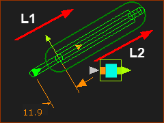
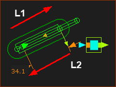
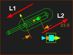
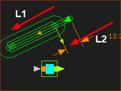
Always, the Positive Direction of a Motion-Dimension for a Slider : '...is the Positive Direction of the Line, or CAD-Line, that is a child to the Part that is kinematically-defined before you add the Motion-Dimension FB to the Slide-Joint. What is the Positive Direction of a Line, CAD-Line, or Part? The direction in which you drag - from its start-Point to its end-Point - when you add the Line, CAD-Line, or Part. Examples: positive direction of Sliders •Line 1 is a child to a Part that is kinematically-defined before you add the Motion-Dimension FB •Line 2 is a child to a Part that is kinematically-defined after you add the Motion-Dimension FB I have used the red arrows to show the direction in which I dragged my mouse-point to add the Lines and Parts. |
||
|
•Line 1 – L1 in the Base-Part- Drag up to the right •CAD-Line/Part 2 – L2 - Drag up to the right The Motion-Dimension is 11.9mm. If you Increase the Motion-Dimension value, you move the Slider up to the right. The small arrowhead shows the positive direction of the Slider. |
|
|
•Line 1 – L1 in the Base-Part - Drag up to the right •CAD-Line/Part 2 – L2 - Drag down from the left The Motion-Dimension is 34.1mm. If you increase the Motion-Dimension value, you move the Slider up to the right. The small arrowhead shows the positive direction of the Slider. |
|
|
•Line 1 – L1 in the Base-Part - Drag down from the right •CAD-Line/Part 2 – L2 - Drag up from the left The Motion-Dimension is 23mm. If you increase the Motion-Dimension value, you move the Slider down to the left. The small arrowhead shows the positive direction of the Slider. |
|
|
•Line 1 – L1 in the Base-Part - Drag down Right to Left •CAD-Line/Part 2 – L2 - Drag from Right to Left The Motion-Dimension is 13.2mm. If you increase the Motion-Dimension value, you move the Slider down to the left. The small arrowhead shows the positive direction of the Slider. |
|
