Pin-Joint
See also:
If a Pin-Joint is a Power-Source, see Edit Pin-Joint dialog : Motor and Gearbox sizing
Else see Pin-Joint dialog
 Pin-Joints in MechDesigner |
 Pin Joint: Connecting-Rod and Piston |
 Pin-Joint in CAD model. |
Terminology
Pin-Joint : |
A Pin-Joint makes a Point* in a Part to be coincident with a Point* in a different Part**. A Pin-Joint allows two Parts to rotate relative to each other. A Pin-Joint removes two degrees-of-freedom from the model. |
rotating-Part : |
A Part that can rotate relative to a different Part. |
Revolute-Joint : |
The kinematic term for a Pin-Joint. |
Kinematics-Tree : |
In Dyads, we represent a Pin-Joint with the letter R, which is from the kinematic term: Revolute-Joint. |
* Point, start-Point, end-Point, center-Point, or Motion-Point ** Part or Base-Part |
|
Pin-Joints in the graphics-area
 |
A Pin-Joint has two symbols.
|
Simple Case - Add Pin-Joint
 |
STEP 1: Start the Add Pin-Joint command
STEP 2: Select two(2) Points: At least one Point must be in a free Part.
The two(2) Points are now coincident at the Pin-Joint. If the “Select-Elements dialog” opens, see Special-Case. |
|||
Two Pin-Joints |
||||
See also: |
||||
VIDEO : Add Pin-Joint - Simple-Case

Video: Add Pin-Joint (Simple Case)
Special-Case - Add two or more coincident Pin-Joints
Frequently, a design has Pin-Joints that are coincident, to join more than two Parts. Example: You want to join Points(#1,#2,#3), in Parts(#1,#2,#3). with Pin-Joints(#1,#2). Pin-Joint#1 is between Points #1 and #2 (in Parts #1 and #2) When you add Pin-Joint#2, you have two(2) options: •Option A: Pin-Joint#2 is between Points #3 and #1 (in Parts #3 and #1) OR •Option B: Pin-Joint#2 is between Points #3 and #2 (in Parts #3 and #2) To select Option A or Option B is important if you also select the Pin-Joints to add Motion-Dimension FBs. |
|||||
 |
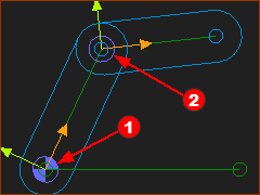
Preparation example:
|
||||
 |
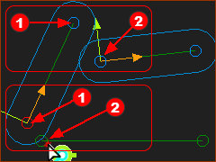
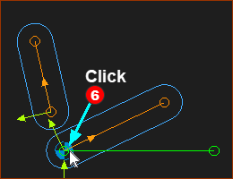
STEP 1:Add Pin-Joint #2
You have actually clicked a total of three(3) Points. •One Point at •Two Points at However, the Pin-Joint is between two(2) Points. Therefore, there is ambiguity ... ... Which two(2) Points, of the three(3) Points, do you want the Pin-Joint to select? Definition: Ambiguity: we are not clear which element(s) to select to add a new element. |
||||
 |
|||||
 |
Select-Elements dialog
Top-Tip
|
||||
 OPTION A |
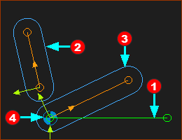
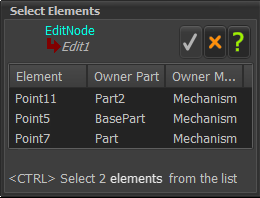
STEP 2:Select the Points in the Select-Elements dialog:
Which two Points do you select from the three Points? There are three options to select two(2) elements from three(3) elements. •Option A: Two elements are compatible or NOT compatible. •Yes, you can select Point11 and Point5 |
||||
 OPTION B |
OR •Option B: Yes, you can select Point11 and Point7. |
||||
 OPTION C |
Option C: No, you cannot select Point5 and Point7. Why? Because Point5 and Point7 are joined with a Pin-Joint, already. Note: In the image to the left, see the word 'not' in the message that is below the element-box “Two selected elements are not compatible” |
||||
Option A |
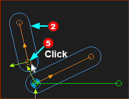
STEP 2:To confirm again, select the TWO Points:
The Select-Elements dialog closes. The Points (and completely free-Part) are coincident, at the new Pin-Joint. |
||||
Top-Tip:
|
|||||

VIDEO - Add Pin-Joint - Special-Case:
Add Pin-Joint - Special Case