Feedscrew ( Scroll)
See Add Scroll
We have labeled the dialog as Feedscrew and Scroll because they are both common terms.
Other terms for Feedscrew:: Worms, Infeed Screws, Gusanos, and Tortillas sin fin.
Use the Feedscrew (Scroll) dialog to:
•Set the number-of-points along the feedscrew surface for each 'rim'
•Set the Start and End - the 'range' - of the 3D-Cam
•Edit the display of the feedscrew in the graphics-area
•Export the feedscrew to SolidWorks®
•Rebuild the feedscrew with the current or active settings.
•Save the feedscrew data that defines the surface mesh.
To Open the Feedscrew dialog
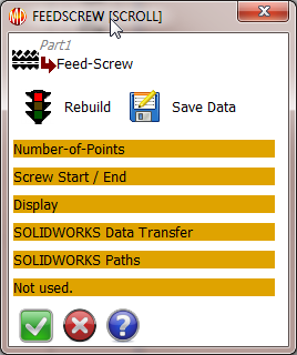
Feedscrew dialog
|
Buttons at top of dialog
Rebuild and Save Data buttons
•Use the Rebuild button to
ore-calculate the points along each 'rim' when you change a parameter
obefore you use the Save Data button
obefore you transfer the Feedscrew to SolidWorks
•Use the Save Cam button to save the feedscrew mesh data as text files.
|
Number of Points
|
Preamble:
•We specify a Feedscrew with a surface.
•There are a number of lines, that we call Rims, along the feedscrew surface.
•There is one Rim for each Motion-Point as defined by the Motion-Path FB.
•There are a number-of-points along each Rim.
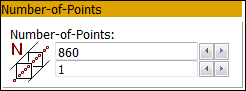
Parameters:
Number-of-Points:
Number-of-points along each Rim. - 860 in dialog to left
|
Screw Start/End
|
Preamble:
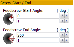
When you add a Feedscrew, we calculate for you the surface for a complete cycle of the MMA : 0 – 360
Use this separator to edit the range of the MMA for which you want to calculate the feedscrew.
The Number-of-Points along each rim does not change.
Parameters:
Feedscrew Start-Angle
•Edit the Start-Angle
Feedscrew End-Angle
•Edit the End-Angle |
Display
|
Preamble:
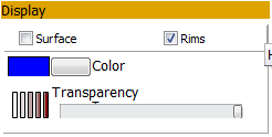
The 'MechDesigner Display' edits how the surface of the Feedscrew shows in the graphics-area.
Controls:
'Surfaces' ; 'Rims' check-boxes
Use the check-boxes to Show or Hide Surface, and Show or Hide Rims.
Solids: show or hide, with the color in the 'color' control, and with the Transparency given by the 'Slider'.
Rims: show or hide the Rims along the Feedscrew.
Color
•Use the Windows color picker to select a color for the Feedscrew and Rims.
Transparency
•Use the slider to change the Transparency of the Feedscrew.
|
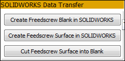
SOLIDWORKS Data Transfer
|
Preamble: When you have set the correct parameters in this dialog: Number-of-Point and Start/End Angles, then you can export the Feedscrew to SolidWorks. To do this
1.Open SolidWorks
2.Add and Save a new Part
3.Make sure the new Part is the 'active' document in SolidWorks
Buttons:
Create Feedscrew Blank in SolidWorks
•We export for you the sketch of the Feedscrew Blank and its Axis-of-Rotation'
•We instruct SolidWorks for you to use the Feedscrew Blank and Axis to add a 'Revolved' feature
Create Feedscrew Surface in SolidWorks
•We export for you the XYZ data of each Rim to a 'Curve' feature
•We instruct SolidWorks for you to use the Curves to Insert a Boundary Surface feature.
Cut Feedscrew Surface into Blank.
•We instruct SolidWorks for you to cut the Revolved feature with the Boundary Surface
See Troubleshooting below.
|
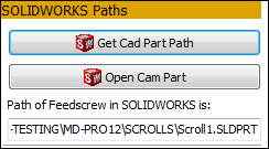
SOLIDWORKS Paths
|
Preamble:
After you have sent the Feedscrew to SolidWorks, it is often useful to link the its file-name in SolidWorks with the Feedscrew element that is in MechDesigner. At a later date, when you open this Feedscrew dialog again, you can reopen the part in SolidWorks.
Buttons:
Get Cad Part Path button: Click this button to link the CAD file-name in SolidWorks with the Feedscrew.
The file-name, with its full path, is put into the 'Path of Feedscrew in SolidWorks is :
Open Cam Part button: Click this button to open the part with the file-name in the 'Path of Feedscrews in SolidWorks is' box.
Before this is possible:
1.You have previously transferred a Feedscrew to SolidWorks and saved the file,
AND
2.You have already clicked the button 'Get Cad Part Path' button. |
|
|
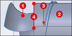
The last command: 'Cut Feedscrew Surface into Blank'  may not work. may not work.
CHECK 1: In SolidWorks, inspect the length of the Scroll Blank relative to the Scroll-Surface relative to the Scroll-Surface . .
In the image to the left, the left of the Scroll-Blank is to the left of the end of the Scroll-Surface. is to the left of the end of the Scroll-Surface.
In this case, the 'Cut Scroll Surface from Blank' (button in dialog) does not work.
|
|
You must, in SolidWorks, or MechDesigner
1.Edit the sketch of the Scroll-Blank
I prefer to edit the sketch in SolidWorks.
|
|
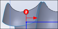
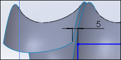
2.Move the end of the sketch to the right of the end of the Scroll-Surface.
In this sketch, I have added a dimension between the end of the Scroll-Surface and the left of the Sketch-Blank.
|
|
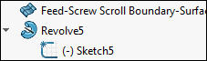
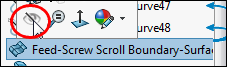
To help, I have, in SolidWorks, dragged the 'Revolve' feature to below 'Feed-Screw Scroll Boundary-Surface'.
Then, as I edit the sketch for the Sketch-Blank I can see the end of the Scroll-Surface.
|
|
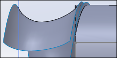
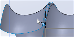
CHECK 2: After you close the sketch and rebuild the model. the Surface-Cut feature in SolidWorks might cut to the incorrect side of the Scroll-Surface - see image to the left. In this case:
|
|
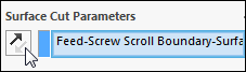
1.Edit the Feed-Screw Scroll Boundary-Surface feature in SolidWorks
2.Click the direction arrow - see image- to reverse the direction of the Cut. |
|
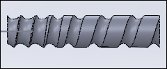
In the image, you can see the Scroll-Blank has been cut correctly by the Scroll-Surface.
However, the Feed-Screw Scroll Boundary-Surface feature is still shown in the model
|
|
CHECK 3: Edit the Feed-Screw Scroll Boundary-Surface feature to hide it from the display.
See image.
|
|
Finally, the scroll is correct.
|
 Trouble-shooting the Feedscrew in SOLIDWORKS