Pattern FB
See Add Pattern FB
Use a Pattern FB to make Copies of Profile/Extrusions (MD-Solids) and/or CAD-Solids at different phases of the machine-cycle - see Solids,
•The Pattern FB anticipates the motion of each Copy and puts each Copy at a position that agrees with its phase of the machine-cycle.
•The Pattern FB can show or hide a Copy for a machine-cycle.
•The Pattern FB can use a timing-chart to show or hide Copies as they pass through different phases of the machine-cycle.
Use Visibility toolbar > Show Solids in Mechanisms to see the Copies that we generate for you with the Pattern FB.
|
To open the Pattern FB dialog:
|
|
The Pattern FB dialog is now open. |
||
Pattern dialog
 Pattern FB dialog |
There are two tabs in the Pattern FB dialog: Pattern ElementsPhase Visibilities |
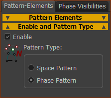
Pattern Elements tab
 |
|
|
 Pattern-Elements |
||||||
Pattern-Elements
Motion to Linearize
|
||||||
Add SOLIDS to the Pattern-Elements box
Solid elements are now in the Pattern Elements box as Extrusions and/or CAD-Lines. To add a Motion FB to the Motion to Linearize box
A Motion FB is now in the Motions to Linearize box To remove a Solid
|


Phase Visibilities tab
Phases are the number of copies of the Pattern-Elements and the machine-angles to show or hide them.
 |
|
# Copies: from 1 to 100 : The number of copies of the Pattern-Elements in the Pattern. The format of the Phases separator is slightly different for the Space Pattern and the Phase Pattern. IF Space Pattern Start Angle, Final Angle: •The Copies show at equal intervals from the Start Angle to the Final Angle. IF Phase Pattern Final Angle = ?- default =360. The concept of a Motion-Period is important. If Final Angle is 360, then the Motion-Period is equal to 1 Machine-Cycle If Final Angle is, for example, 20º, the Motion-Period is 20º. •The # Copies show at regular intervals within one Motion-Period, from MMA=0 to Final Angle. •The Phase Pattern repeats one time for each Motion-Period or 36 ∕ 20 = 18 times in 1 Machine-Cycle. •You can show or hide each Pattern Element within each Motion-Period - see Phase Visibility separator. |
|
Hide Source Pattern Element: Source Pattern Elements are the Solids (CAD-Solids and/or MD-Solids) that you select in the model as Pattern-Elements, and show in the Pattern Elements separator of the Pattern-Elements tab. Nearly always, enable Hide source Pattern-Element. This is because the Copy #1 and the source Pattern-Element are at the same position 1.Click a Pattern-Element in the Pattern Elements separator and Pattern-Elements tab. It should show in the Phase-Visibilities separator (to see you have selected it). 2.Click the Hide Source Pattern Element check-box. Copies Box |
|
 |
•To hide a Copy for the total Motion-Period, click a •To show a Copy for the total Motion-Period, click a |
 Phase-Visibilities > Pattern-Visvibility |
Note: Pattern Visibility Use Pattern Visibility to show or hide a Pattern-Element for different periods within the Motion-Period. |
|
To edit the Visibility of a Pattern-Element:
The Pattern Visibility interface is now open. You can now edit the Visibility of the element that is in the Pattern-Element to Edit |
||
How to use the Pattern Visibility interface
Refer to the image below:
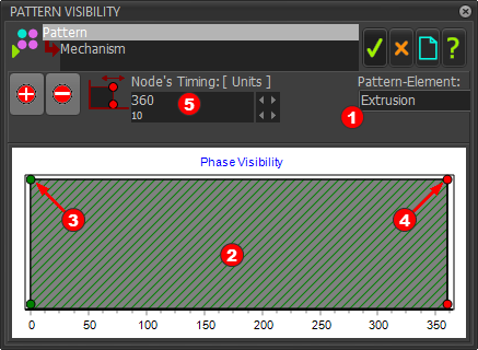
As an example: In the image below, there is one Visible-Period of the Pattern-Element “Extrusion”, from 0º to 360º. |
||
 |
||
There are two(2) Nodes that control the timing of each Visible-Period.
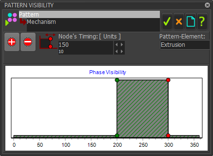
To edit a Visible-Period for the Pattern-Element you must edit the timing of the Start-Node and/or End-Node. STEP 1.(Example) Edit the Start-Node and End-Node to define a Visible-Period.
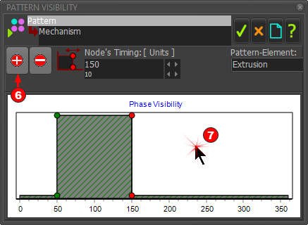
The image below shows the new timing of the Visible-Period for the Pattern-Element (Extrusion). It starts at 50 and end at 150 in the Machine-Cycle. |
||
 |
||
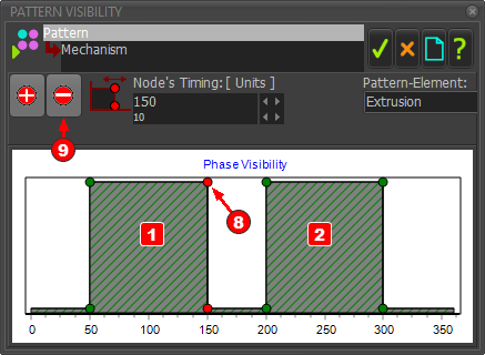
STEP 2.(Example continued...) Add a new Visible-Period
There is now a new Visible-Period in the Phase-Visibility Chart - see image below. STEP 3.(Example continued...) Edit the Start-Node and End-Node to define the timing of the new Visible-Period.
The image below shows the two Visible-Periods in the Phase-Visibility Chart for the Pattern-Element (Extrusion) Visible Period Visible-Period |
||
 |
||
STEP 4.(Example continued...) Delete a Visible-Period
The image below shows one Visible-Period in the the Phase-Visibility Chart for the Pattern-Element (Extrusion) You can now Click |
||
 |
Pattern Visibilities - example
Imagine a chain wrapped around a circular, 12-hour, analog, clock. There are 12 hours and 12 chain-links in the chain.
The chain moves continuously around the circular clock.
To add the 12 copies of the Pattern-Element (see Pattern-Elements tab chain-links is the Source Pattern-Element (Solid).
•Edit Phase Visibilities tab > PHASES separator > # Copies to edit the number of chain-links on the chain - in this example, 12 copies to give 12 chain-links.
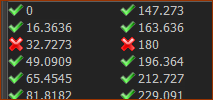
You will see in the box below the angle of the 12 Copies, when the MMA=0.
•Click a copy in the table.
The ![]() changes to a
changes to a ![]() for each copy you click.
for each copy you click.
A ![]() next to the copy means you can see the copy move around the clock - however, see also Pattern Visibilities
next to the copy means you can see the copy move around the clock - however, see also Pattern Visibilities
A ![]() next to the copy means you can not see the copy, as it moves all the way around the clock.
next to the copy means you can not see the copy, as it moves all the way around the clock.
•Nearly always, enable Hide Source Pattern-Element.
•Use Pattern Visibility to hide each chain-link, one link after the next link, as it moves between hours, for example, between 6 and 9 o'clock.