Math FB (with Calculator)
See Add Math FB See also : ![]() Tutorial 18: Math FB
Tutorial 18: Math FB
Use a Math FB to add new math functions.
Use a Math FB to change units of a Data-Type. For example, change units from motion (P, V, A) to Force (Newtons).
There is a Calculator interface to help you add different functions.
|
To open the Math FB dialog:
|
|
The Math FB dialog is now open. |
||
 Math FB dialog |
Math FB Interface
1.Click the button to add an input-connector to the Math FB. You need one input-connector for each variable or parameter in your equation. Note: If you connect a wire from a Motion FB to the input-connector of a Math FB, then select Linear or Rotary as the Output Data-Type in the Motion FB. |
1.Click the button to add an output-connector from the Math FB. You need one output-connector for each output. |
1.Click the button when you: •open the Math FB dialog •Add an input-connector or an output-connector •Change the Output Data-Type •Edit an equation |
The units of the Output Data-Type apply to All of output-connectors from the Math FB. To select a different Output Data-Type 1.Click the drop-down box 2.Select an Output Data-Type 3.Click the button Note: Inside the Math FB, all units are SI units. A change to the Output Data-Type may change the values at the output-connector of the Math FB. |
Equations
Output Data-Type, Output-Connectors, Data-Channels
For example: If you select Linear Coordinates as the Output Data-Type, then the output of ALL equations have Linear Units If you have two(2) output-connectors, there are 6 equations. •The units for Data-Channels Q0[Dis.] and Q1[Dis.] are Displacement, with units of •The units for Data-Channels Q0[Vel.] and Q1[Vel.] are Velocity, with units of •The units for Data-Channels Q0[Acc.] and Q1[Acc.] are Acc, with units of •Data-Channels/Equations 0, 1, 2 are for the Output-Connector #1 •Data-Channels/Equations 3, 4, 5 are for Output-Connector #2 |
Wire Numbers / input-connectors and Data-Channels
The image below shows three Wires connected to three Input-Connectors. |
|
 3 Wires, 3 Input-Connectors |
Wire Numbers - refer to the image. Wire numbers start at 0 •Input-Connector 1 is for Wire 0 - connected to the TOP input-connector •Input-Connector 2 is for Wire 1 •Input-Connector 3 is for Wire 2 - connected to the BOTTOM input-connector |
Data-Channels Each wire has 3 data-channels. Each Data-Channel is designated a letter: •p = Data-Channel 1 •v = Data-Channel 2 •a = Data-Channel 3 The format of an Equation references a Wire-Number and a Data-Channel: Data-Channel (Wire-Number) Example - Entries in an Equation: p(0) : p refers to Data-channel 1 ; and (0) refers to input-connector 1 a(2) : a refers to Data-channel 3 ; and (2) refers to input-connector 3 v(1) : v refers to Data-channel 2 ; and (1) refers to input-connector 2 |
|
How many input and output-connectors?
As an example, to calculate Power : P = Ʈ . ω Power (N.m./sec) = Torque(N.m.) × Angular Velocity (rad/sec) Torque and Angular-Velocity are inputs to the equation. Power is the output. You need two input-connectors and one output-connector. Edit the Math FB to open the Math FB dialog. 1.Add two Input-Connectors with the Add-Input button 2.Select Power as the Output Data-Type 3.Click the UPDATE button |
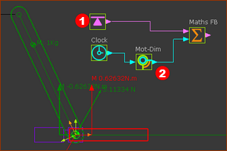 |
Prepare the model (see above) 1.Add a Rocker - see Tutorial 1 2.Edit the CAD-Line of the Rocker, to open the CAD-Line dialog. In CAD-Line dialog > Mass Properties tab > User Mass Properties : Enter a value for the Mass. Enter X and Y values to move the Center-of-Mass away from the start-Point (origin) of the CAD-Line. 3.Use Forces menu >Force-Data FB to the model ; 4.Edit the Force-Data FB. In the Force-Data dialog ; select the Pin-Joint, and select the Point in the Base-Part to to analyze the Torque that acts-on the Base-Part. |
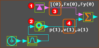 |
See image above - the Data-Channels from the output-connectors of: •Force-Data FB •Motion-Dimension FB The Math FB uses SI units for all data 'inside'. Enter the Equation Click the first equation in the Math FB The Equation-Editor opens - see below. You need to enter this equation: Q0 [Power] = p(0)*v(1) |
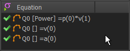 |
p(0) = Channel 1 (p = Torque), Wire-Number 0 (top input-connector) × v(1) = Channel 2 (v = Angular Velocity), Wire-Number 1 (input-connector below top) |
SYNTAX and VALID Equations Click Update button to confirm that the syntax of the equation correct. For example, it may not have correct number of parentheses. The reason is given as a message in the Feedback-Area. The IMPORTANT Data from Motion FBs If you connect a wire from a Motion FB to the input of a Math FB, select the Output Data-Type in the MOTION FB as Linear or Rotary. |
MORE ABOUT UNITS 'inside' the Math FB
The data-values at the output connector of a Math FB can be confusing for these reasons: A: SI Units Inside the Math FB, the units are SI e.g. meters (m). But the wires that connect to the input-connector of a Math FB may have motion-values that are millimeters (mm). B: SI Units are converted to the Engineering Units of the Output-Data-Type. The SI units and values (internal to the Math FB) are converted back to Engineering Units for the Output Data-Type that you select. Example: •If a Motion FB is set to Rotary, and the output from it is 90º, then the value internal to the Math FB is 1.57radians. •If the Motion FB is set to Linear, and the output from it is 100mm, the value internal to the Math FB is 0.1m. Example continued... If you multiply these two values in the Math FB dialog, the internal result is 0.157. •If the Output Data-Type is set to Rotary Coordinates, the output is 9º. Or 0.157rads (inside the Math FB) = 9º (outside the Math FB). •If the Output Data-Type is set to Linear Coordinates, the output is 157mm. Or 0.157 meters (inside the Math FB) = 157mm (outside the Math FB). Note The example assumes the Engineering Units are set to “degrees” and “millimeters” C: If you connect an output from the Math FB to a Slider with the Data-Type set as Rotary-Coordinates : Rotary units to move a Linear Slider! (The Engineering-Units are “degrees” and “millimeters”) In the Math FB, if you set the Output Data Type to Rotary Coordinates, then 0.157 is 0.157rads internally to the Math FB. It is 9º at the output. If you connect the Math FB to a Motion-Dimension FB to move a Slider, then the 9º is 9mm. D: If you connect an output from the Math FB to a Rocker, with the Data-Type set to Linear-Coordinates : Linear Units to move a Rotary Rocker! (The Engineering-Units are “degrees” and “millimeters”) In the Math FB, if you set the Output Data Type to Linear Coordinates, then 0.157 is 0.157m internally. It is 157mm at the output. |
Equation-Editor with Calculator
 Equation-Editor with Calculator |
The Equation-Editor provides a few of the common mathematical functions you can add to each equation. When open and close brackets show within a function button, you should enter a value that is constant or a value that changes over a machine-cycle. For Example: Sin( ) You can enter a constant. E.g. Sin(3.14) You can also enter a variable. E.g. Sin(p(1)) p(1) is data-channel #1 of input-connector #2. Calculator Functions1.Position, Velocity, and Acceleration Values for a linear and angular motion-values at the input-connector. •P( ) ; V( ) ; A( ) 2.Standard Algebra •Arithmetic: +, –, ∕ , * •Power: ^ •Brackets: ( ) 3.Boolean •> : <output> = 1 if <value 1> > <value 2>, else 0 •< : <output> = 1 if <value 1> < <value 2>, else 0 4.Trigonometry (all inputs in radians) •Standard: Sin( ), Cosine( ), Tangent( ) •Hyperbolic: Sinh( ), Cosh( ), Tansh( ) •Inverse: ArcSin( ), ArcCos( ) , ArcTan2( ; ) 5.Limit (input ; maximum value ; minimum value) : <output> = <input> if <input> is less than maximum value AND more than minimum value. <output> = <maximum-value> if <input> is greater than maximum <output> = <minimum-value> if <input> is less than minimum 6.OverLimit (input ; limit-value) : <output> = <input> if <input> is 'greater than limit-value' <output> = <limit-value> if <input> is 'less than limit-value' 7.UnderLimit (input ; limit value) : <output> = <input> if <input> is 'less than limit-value' <output> = <limit-value> if <input> is 'greater than limit-value' 8.Limits (input ; maximum value ; minimum value) : <output> = <input> if <input> is 'greater than maximum value' OR less than minimum value'. <output> = <maximum-value> if <input> is 'less than maximum' AND 'more than minimum-value <output> = <minimum-value> if <input> is 'greater than minimum-value AND 'less than maximum-value' 9.Numerical Keypad 10.1...9, 0, Π. 11.Abs( ) 12.Mag( ; ) (assumes the two values are 'orthogonal' and uses Pythagoras to find the 'resultant') 13.Sqrt( ); 14.DegToRad( ) 15.RadToDeg( ) |
Limit Functions:
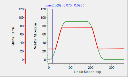 |
Limit Function Limit (input ; maximum value ; minimum value) : <output> = <input> if <input> is less than maximum value AND greater than minimum value. <output> = <maximum-value> if <input> is greater than maximum <output> = <minimum-value> if <input> is less than than minimum E.g Limit(p(0),0.08,0.025) Note Arguments in the Limit Function are SI units for the units in the model. For example, 75 millimeters in the model is 0.075 meters in the function. |
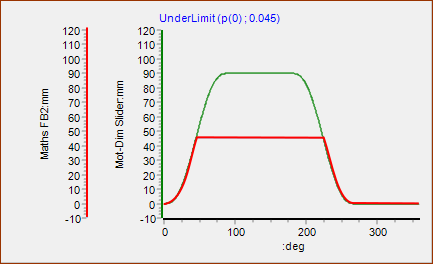 |
Under-Limit Function UnderLimit (input ; limit value) : <output> = <input> if <input> is 'less than limit-value' <output> = <limit-value> if <input> is 'greater than limit-value' |
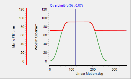 |
Over-Limit Function OverLimit (input ; limit-value) : <output> = <input> if <input> is 'greater than limit-value' <output> = <limit-value> if <input> is 'less than limit-value' |