Summary of this Step:
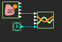
1.Add a Cam-Data FB and Graph FB 2.Link the Cam-Data FB to the 2D-Cam 3.Connect a wire from the Cam-Data FB to the Graph FB 4.Plot the Pressure Angle of the 2D-Cam with a Graph FB |
Video
STEP 1: Add a Cam-Data FB to the graphics-area
The Cam Data FB is now in the graphics-area. |
|||||
 |
In the graphics-area, the Cam-Data FB is larger than other Function-Blocks. We must link the Cam-Data FB to a 2D-Cam. The Cam-Data FB has five output-connectors. After you link the Cam-Data FB to a 2D-Cam, one of the output-connectors is Pressure-Angle of the 2D-Cam. See below : Cam-Analysis - Pressure-Angle |
||||
 |
||
STEP 1: Open the Cam-Data FB
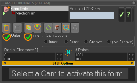
The Cam-Data dialog is open - see above. |
||
 |
||
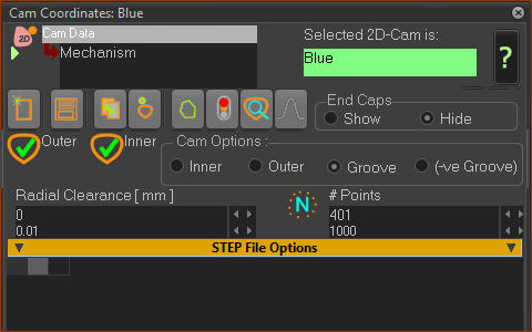
Link the 2D-Cam to the Cam-Data FB. STEP 2: Link the Cam-Data FB to the 2D-Cam
The name of the 2D-Cam is in the Selected 2D-Cam box. Note: In this case, I have renamed the 2D-Cam to Blue ! This helps me identify the 2D-Cam in the graphics-area when there is more than one 2D-Cam in the model. I will use the 2D-Cam dialog to change the color of the 2D-Cam in the graphics-area to Blue of course. STEP 3: Close the Cam-Data FB dialog
|
![Cam Data FB output-connectors [Note: Entrainment-Velocity is available from R14+] Cam Data FB output-connectors [Note: Entrainment-Velocity is available from R14+]](gst-6a8-ga-fb-camdata.png) Cam Data FB output-connectors |
There are five(5) output-connectors from the Cam-Data FB. To calculate the Contact-Force and Contact-Stress between the Cam-Profile and the Follower-Profile, the Parts in the Follower kinematic-chain must have mass and inertia properties. In this tutorial, we have not added mass or inertia to the Parts. We can also analyze the •Pressure Angle •Radius-of-Curvature •Sliding Velocity In this tutorial we will analyze the Pressure-Angle. |
|||||
 |
STEP 1: Add a Graph FB to the graphics-area.
STEP 2: Connect a wire from the Cam-Data FB to a Graph FB
|
|||||
The Pressure-Angle of a Cam is an important parameter to analyze. A high Pressure-Angle means that the force/torque is not transferred from the Cam-Part to Follower-Part efficiently. But, the Follower-Part does transfer Forces and Torque efficiently to the Cam-Shaft. This tends to increase the rotational-speed of the Cam-Shaft. The Pressure-Angle imposes extra forces on the machine elements in the Cam and the Follower kinematic-chains. The forces increase rapidly when the Pressure-Angle is greater than 40° (an arbitrary angle as it depends on what is being driven by the cam). Many designers aim to keep the Pressure-Angle between ±30°. See Tutorial 7, Design-Set - where you reduce the Pressure-Angle to these limits. See Tutorial Forces 13 for force analysis. |
||||||