Summary of this Step
Before we can do Add 2D-Cam, we must add a Cam-Shaft. The Cam-Shaft is a Part that rotates with constant angular velocity. Identical to Tutorial 1. |
Video of this Step

'Expand' then 'Play'
 |
Notes: A: In Step 6A.3 we added a Line B: It is possible to add a Pin-Joint and a Part at the same time. |
|
 |
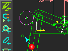
STEP 1: Add a Part as the Cam-Shaft
We join the start-Point of the Part to the start-Point on the Line, with a Pin-Joint. |
|
Note:
|
||
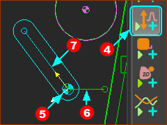 |
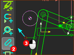
STEP 2: Add the Motion-Dimension FB
The Motion-Dimension FB is next to your mouse-pointer. The Cam-Shaft is now a Part that is kinematically-defined (Solved) |
|
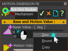 |
STEP 3: Edit the start angle of the Cam-Shaft Edit the angle of the Cam-Shaft so it is horizontal when the MMA is at 0.
The Cam-Shaft is now horizontal when the MMA = 0. |
|
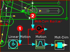 |
STEP 4: Connect the Linear-Motion FB to the Motion-Dimension FB You can connect more than one wire from the output-connector of a Linear-Motion FB.
STEP 5: Cycle your model Use the ALT+C key combination. Save your mechanism You can connect one wire to the input-connector of a Function-Block. A Function-Block may have many wires from its output-connector to connect to other Function-Blocks. |
|


